The following equations provide an estimate of the potential capabilities of a telescope.
It’s important to note that these equations are theoretical and actual performance may vary based on the quality of the telescope, proper calibration, and atmospheric conditions.
The telescope’s magnification (G)
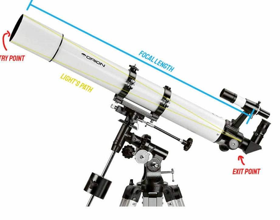
G=F/f where F represents the focal length of the objective lens and f represents the focal length of the eyepiece.
While you usually can’t alter F, you can vary the magnification or magnifying power of the telescope by using eyepieces with different f values. The telescope’s magnification G.
Maximum magnification (G max)
The highest level of magnification that can be achieved is referred to as maximum magnification, or G max.
Luminosity
The luminosity of a telescope is determined by the ratio D:F. If you don’t give it much thought, a smaller ratio indicates a better telescope for observing galaxies and nebulae (e.g. 1:5). On the other hand, a telescope with a longer focal length and a ratio like 1:12 is ideal for observing the Moon.
Definition of Resolution (b)
Resolution refers to the smallest angle between two stars that can be observed as separate entities, rather than appearing as a single merged object. In simpler terms, resolution can be thought of as the level of “sharpness” in an image (apologies to the experts in optics).
b=138/D, where D represents the aperture of the telescope lens. This measurement is typically expressed in seconds (or more specifically, arc seconds).
Due to atmospheric conditions, the resolution is usually not less than 1″ (1 second). To provide some context, on the Moon, 1″ is equivalent to a crater with a diameter of approximately 2 km.
For long focal length lenses, with aperture values of 1:12 or greater, the formula slightly differs: b=116/D (Dunlop).
It is evident from the information provided that, under normal circumstances, a minimum resolving power of 1″ can be achieved with a reflector telescope having an aperture of approximately 150mm, while for planetary refractors, an aperture of about 125mm is required. Theoretically, telescopes with larger apertures offer a clearer image, especially in areas with clear atmospheric conditions such as high mountain regions or on those fortunate days when the weather is favorable.
However, it is important to consider that larger telescopes not only provide brighter images but also allow for the observation of fainter details and objects. Therefore, from the perspective of an average observer, larger telescopes still offer superior image quality compared to smaller ones.
Furthermore, there may be brief periods of time when the atmospheric turbulence subsides to such an extent that a larger telescope can deliver a clearer picture than the 1″ limit, while a smaller telescope would still be restricted by this limit, resulting in a frustrating experience.
Thus, it is not advisable to confine oneself to a 150mm aperture limit. 😉
Limit of Stellar Magnitude (m)
The maximum magnitude of a star that can be observed through a telescope is determined by its aperture size:
m=2.1+5*lg(D) where D is the diameter of the telescope in millimeters and lg represents the logarithm.
Calculating this equation reveals that the largest available telescope with a 300 mm aperture has a limiting stellar magnitude of approximately 14.5 m. Fainter objects are observed using photography and subsequent computer processing of images.
For reference, here is a table showing the relationship between telescope aperture D and the corresponding limiting stellar magnitude:
| 32 | 9.6 | 132 | 12.7 |
| 50 | 10.6 | 150 | 13 |
| 60 | 11 | 200 | 13.6 |
| 70 | 11.3 | 250 | 14.1 |
| 80 | 11.6 | 300 | 14.5 |
| 90 | 11.9 | 350 | 14.8 |
| 114 | 12.4 | 400 | 15.1 |
| 125 | 12.6 | 500 | 15.6 |
Exit pupil
The exit pupil is an important optical parameter that can affect the overall viewing experience. It refers to the diameter of the beam of light that exits an optical system, such as a telescope or binoculars, and reaches the viewer’s eye. The larger the exit pupil, the brighter the image will appear. This is because a larger exit pupil allows more light to reach the viewer’s eye, resulting in a brighter image. On the other hand, a smaller exit pupil can make the image appear dimmer.
The exit pupil is calculated by dividing the diameter of the objective lens by the magnification of the optical system. For example, if a telescope has a 100mm objective lens and a magnification of 20x, the exit pupil would be 5mm (100mm divided by 20x). This means that the beam of light exiting the telescope would have a diameter of 5mm.
The size of the exit pupil is important because it should match the size of the viewer’s pupil. The pupil is the opening in the center of the iris that allows light to enter the eye. The average pupil size in humans ranges from about 2mm in bright light to about 7mm in very dim light. If the exit pupil is smaller than the viewer’s pupil, some of the light will be wasted and the image will appear dimmer. On the other hand, if the exit pupil is larger than the viewer’s pupil, the excess light will not enter the eye and the image will not appear any brighter.
In addition to affecting the overall brightness of the image, the exit pupil can also affect the field of view. A larger exit pupil can provide a wider field of view, allowing the viewer to see more of the scene at once. On the other hand, a smaller exit pupil can result in a narrower field of view.
Overall, the exit pupil is an important factor to consider when choosing an optical system, as it can affect both the image brightness and the field of view. By matching the exit pupil to the viewer’s pupil size, the best viewing experience can be achieved.
Field of view of a telescope
The telescope’s field of view is equal to the eyepiece’s field of view divided by L
The eyepiece’s field of view is specified in its passport, and we already know how to calculate the telescope’s magnification G with a given eyepiece: G=F/f.
What is important to know about the telescope’s field of view?
The larger the telescope’s field of view, the more of the sky can be observed, but the smaller the objects will appear.
By knowing the field (angle) that your telescope will capture at a given magnification, and the angular size of the object you are searching for, you can estimate the portion of the field of view that the object will occupy, allowing you to have a general idea of what you will see through the eyepiece.
If you are searching for an object using maps rather than coordinates, it can be helpful to create wire rings that correspond to the angular fields of view of your eyepieces in the telescope. This makes it easier to orient yourself: by moving the telescope from star to star while simultaneously moving the ring on the map, you can easily compare the images.
Now that the relationship between the characteristics of the telescope is roughly clear, one can take a different perspective on what can be observed through telescopes of varying sizes.
Vladimir, I appreciate your humor, but I am not involved in the development of spy equipment 🙂
I am having trouble understanding how to solve this problem.
A camera with a lens focal length of 9 cm captured images of distant objects at the closest possible distance of 81 cm for this device. I need to determine the amount by which the lens had to be moved forward.
Currently, I do not comprehend the condition either. However, assuming that the problem implies that the camera initially captured distant objects and then moved closer to the closest possible distance, it resembles an issue related to the formula of a thin lens:
1/f2 = 1/F – 1/d2 = 1/9 – 1/81 = 9/81 – 1/81 = 8/81;
f2 = 81/8 = 10.125 cm
f2 – f1 = 10.125 – 9 = 1.125 cm.
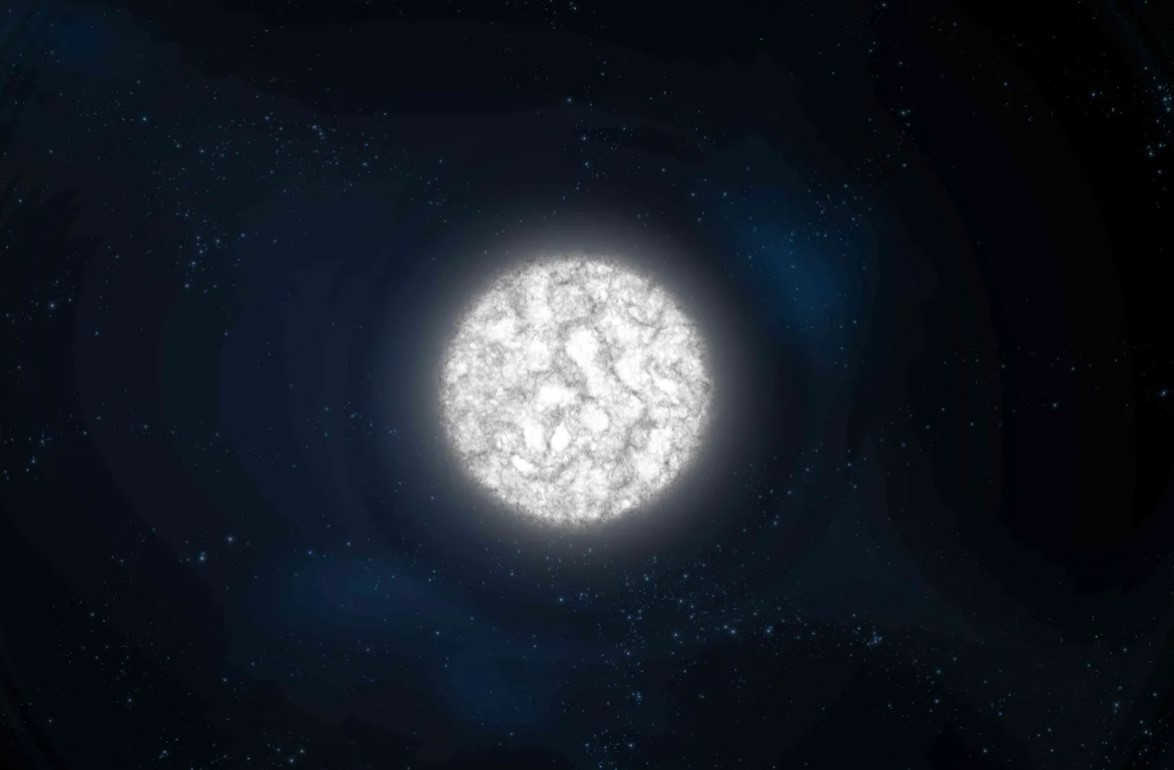
How can one determine (using which formula) the range of a telescope if it is required to observe stars with atmospheric temperatures of, for example, 10000:K?
Knowing the original reason behind this question would be beneficial. Without the specific details, it can be said that a white star with a magnitude of 10000K can be observed through a telescope. However, the visibility may vary depending on the apparent stellar magnitude. For instance, the red color is harder to distinguish and would require a telescope with a slightly larger aperture. On the internet, one can find the sensitivity curve of the human eye and derive a formula based on that. However, this information may not be very useful as amateurs typically observe what is available rather than selecting a telescope specifically for each star.
There seems to be an error in the text: “G max=1.5*D, where D is the focal length of the lens”. I believe it should be: D – the aperture of the lens or the main mirror.
My telescope, the Levenhuk Skyline 76*700AZ, is incredibly basic. It’s quite disappointing that I can only observe the outer edge of a star, while the center remains obscured. I’m curious as to why this is the case. If you have any insights, please share!
Tatiana, February 16, 2020
Tatiana, when using an amateur telescope, the star should appear as a singular point. However, due to various distortions, it may appear as a cluster of deviations. It seems that your telescope’s focus is not properly adjusted, resulting in a “bagel” shape instead of a point-like star. I recommend researching the terms “pre-focal” and “out-of-focal” for reflector telescopes, as there are numerous photos available online illustrating these concepts. In my opinion, your telescope is likely out of focus. Once you are able to adjust the focus, I suggest reading about the process of aligning a reflector telescope, as it is a skill that requires manual fine-tuning. Mirror telescopes, like yours, can be more challenging for beginners compared to lens telescopes. To start, try rotating the focuser adjustment wheel back and forth. This double wheel is located on the part where you insert the eyepiece. It is possible that you may be turning it, but the focuser may not have enough “travel” to adjust properly. However, this is unlikely unless you are using a non-standard interchangeable eyepiece or have inserted the eyepiece incorrectly (which can happen). I recommend starting with the standard eyepiece that came with your telescope.
You mentioned in the article that the approximate diameter of the human pupil in the dark is 6 mm. However, I have come across information stating that our pupil is 8mm in the dark. So, which one is correct?
Elena Alexandrovna, August 16, 2019.
In an ideal case, the pupil is 8mm in the dark. This assumes that the eyes are perfectly healthy, the eye muscles are functioning optimally, and the measurements are taken in complete darkness. However, in real life, our eye muscles often do not work as they should, resulting in a pupil size of around 7mm. Additionally, there is some light coming from the eyepiece of the telescope, which prevents complete darkness and causes the pupil to shrink even further. Therefore, the actual pupil size is approximately 6mm. Furthermore, when looking at the moon, the pupil size may be even smaller. Thank you for your kind words about the article and other articles on our site. We strive to provide clear and detailed information. You’re welcome!
Alexander, August 16, 2019.
Feel free to ask if you need anything 🙂
This article is fantastic. Thank you. Celestron 120/1000 OMNI
This is an incredibly informative and thorough description. It is an essential article for me since I recently started exploring astronomy. My telescope is the Sturman HQ1400150EQ. I really appreciate it!
Response:
You’re very welcome! 🙂 Starting with a 150mm aperture and an equatorial mount is a great choice. Just make sure you find an observing location with minimal light pollution. Best of luck!
Nikolay.
We provide an opportunity to create an affordable and top-notch homemade telescope for aspiring astronomers. It will only cost you up to 15 euros to purchase the necessary lenses, and the resulting image quality will be exceptional and professional. This telescope boasts impressive power, allowing you to observe Jupiter and Venus as if they were globes, witness the majestic rings of Saturn, and explore the countless craters and other features on the Moon’s surface. On a clear night, you can even catch a glimpse of Jupiter’s four largest satellites, known as the Galilean moons, while studying the celestial sky.
Step 1: Lenses and their characteristics
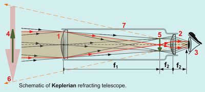
The refractor telescope featured here is a compact Kepler model. With a magnification power of approximately 20 times, it is suitable for initiating astronomical observations of celestial objects. However, it’s important to note that the telescope produces inverted images, making it less ideal for observing terrestrial subjects.
While it is possible to correct the inverted images by incorporating positive lenses into the design, doing so would inevitably compromise the overall image quality due to the introduction of additional optical elements. In the field of astronomy, the ability to invert objects is not as crucial as achieving clear and high-contrast images. Furthermore, when exploring the vastness of the cosmos, the notion of earthly directions becomes insignificant.
The lenses are the key components of a telescope. While you may be tempted to use ordinary glass panes found in old boxes in the attic, there are two important reasons why you should avoid doing so. Firstly, you will not be able to determine the exact focus and it is unlikely that you will be able to find glasses with the optimal parameters for constructing a telescope. Secondly, regular glasses from spectacles or magnifying glasses are not capable of transmitting images without distortion due to the harsh optical conditions.
There are two major problems associated with such lenses: spherical and chromatic aberration. Having one of these issues can completely ruin the image, but these distortions are always present together. As a result, any attempt to construct a telescope using glass lenses or regular magnifying glasses leads to disappointment when the observer attempts to view stars or planets through such a device. The object in this type of telescope appears as a blurry rainbow spot, making it impossible to discern any clear details. Therefore, if you are considering building your own small telescope, it is advisable to avoid using simple lenses and instead follow these instructions to create an affordable, semi-professional instrument.
If you’re looking to purchase these lenses, you can find them available for sale on various online stores. In order to construct your own telescope, you’ll require a total of three lenses. Two lenses should be of the same size, while the third lens should be larger in size. Now, let’s delve into the workings of the Kepler refractor.
Step 2: Understanding the Kepler refractor.
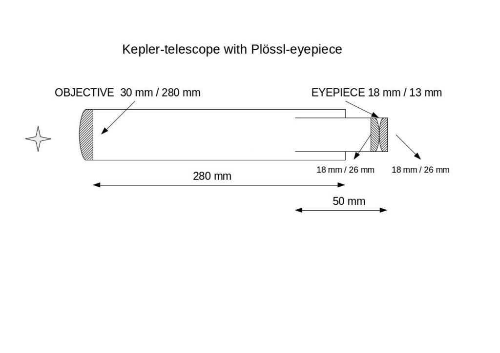
The illustration depicts a traditional and rudimentary technique for enlarging distant objects. Rays of light, traveling in parallel, emanate from an object and reach the large lens of an objective with a long focal length. These rays refract and converge at the focal point before entering a small-diameter eyepiece with a short focal length, which further amplifies the image. The objective lens is responsible for gathering light, while the eyepiece lens facilitates magnification. When combined, the focal lengths of the objective and eyepiece determine the overall length of the telescope, while the ratio between the lenses determines its magnification. By utilizing two identical achromatic lenses, as exemplified in the diagram, a highly effective dual magnification eyepiece known as a Plossl eyepiece is obtained. This particular eyepiece is employed in project 3:
Lens (€5): with a focal length of 250 mm and a diameter of 30 mm, you can identify this lens by the item number 569.OAL.
You can find detailed information about this lens on the AstroMedia website.
To complete the project, you will need one lens of this type.
Ocular (4.6 euro): with a focal length of 26.5 mm and a diameter of 18 mm, you can identify this eyepiece lens by the article number 551.OAL.
For information about this lens, please visit the AstroMedia website.
For the Plossl eyepiece, you will need two lenses of this type. However, for a simple 10x magnification eyepiece, one lens will be sufficient.
Step 3: Necessary Materials and Tools
In addition to the lenses, you will also require several other components.
The following materials are needed:
- The three aforementioned achromatic lenses.
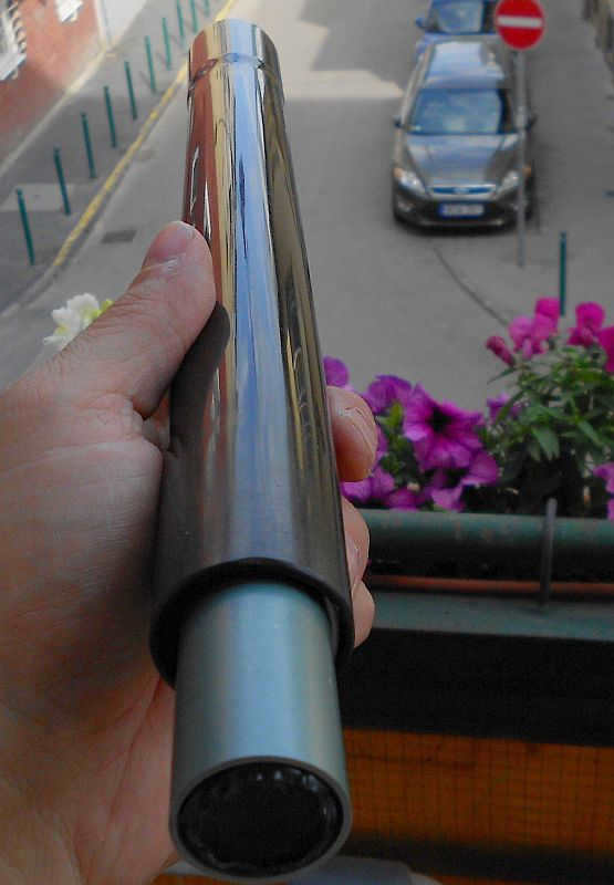
- A vacuum cleaner pipe, either plastic or metal (26-27 cm in length).
- An old thick pen or a small plastic tube (5-6 cm in length).
- Two standard plastic bottle stoppers.
- A sheet of black cardboard (not glossy!)
- Insulating tape.
- A few strips of cardboard.
Step 4: Put together the primary cylinder
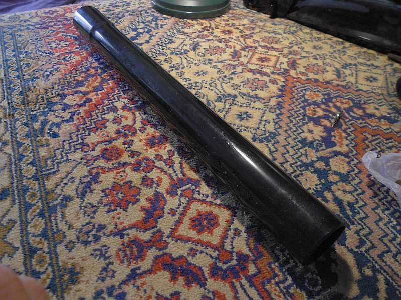
An old vacuum cleaner can provide a useful telescope tube. Its outer diameter measures 30mm, but it features a thickening on one side with an inner diameter larger than 30mm. This makes it perfect for securing the objective lens, and there is even a small lip in front of the lens that acts as a visor, protecting it from any stray light.
The smaller tube, as shown in the picture, serves as the eyepiece tube and can be slid into the main tube. To prevent unwanted glare, insert pre-cut sections of black cardboard into both tubes.
To achieve the desired length (27-28 cm), cut the large tube accordingly. Then, twist a piece of black cardboard into a tube and insert it into the main tube, approximately 20 cm from the wider end. Attempt to insert the objective lens – it should fit easily. Congratulations, you now have a tube with a black inner surface.
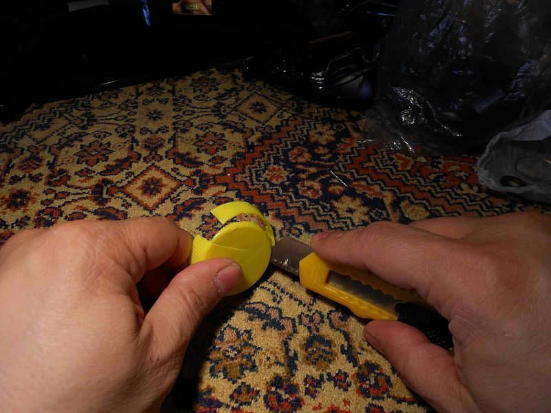
Take two plastic bottle stoppers and trim their edges to create two plastic rings. These rings will secure the lens without the need for glue. Cut small sections from the rings to allow for flexibility when installing them.
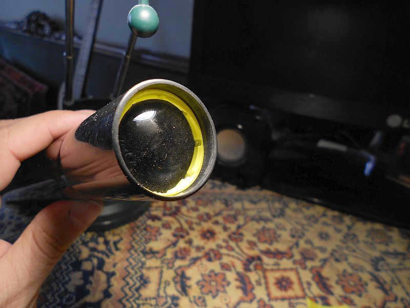
Insert one of the rings all the way into the wider end of the tube, ensuring it is level. Next, carefully insert the large lens (30 mm) with the convex side facing outward and secure it in place with the second ring. You may use a small amount of glue to secure this ring, but be careful not to get any glue on the lens! The lens should be able to move slightly between the two rings. Remember to position the lens with the convex side facing upward towards the sky. The main tube assembly is now nearly complete.
Step 5: Put together the eye tube
The eyepiece tube will have a slight variation compared to the main tube. Locate a plastic tube with an internal diameter of 20 mm and a minimum length of 5 cm. Afterwards, acquire two small lenses for the eyepiece and arrange them with their convex sides facing each other (refer to the photo). This step holds significant importance. By employing this technique, we will obtain a highly efficient Plossl eyepiece. The separation between these lenses should not exceed 1-2 mm.
At this point, it is essential to encase the lenses in duct tape to prevent any movement or tilting. Maintaining axial symmetry is crucial here. Apply enough duct tape to secure the lenses snugly within the eyepiece tube and position them at the tube’s very edge.
The size of the rings’ apertures needs to be determined through experimental selection prior to final assembly.
In order to avoid any visible irregularities in the image, it is crucial that the edges of the inner holes of the aperture rings are perfectly even. To address this issue, a ring punch can be used to create the rings. This process will require some experimentation. One approach is to find a metal washer of the appropriate size and utilize it as a diaphragm. Additionally, explore other potential alternatives.
It is possible to create a basic eyepiece instead of purchasing a Plossl eyepiece, which can help save money. In this case, only one small lens will need to be acquired. The resulting magnification will be approximately halved to around 10x. Even with this level of magnification, it will be possible to observe craters on the Moon (though not on Jupiter or Saturn). If you decide to construct such an eyepiece, make sure to mount the lens with the convex side facing your eye.
Step 6: Final Steps
The telescope is nearly complete, with just one final task remaining: inserting the eyepiece tube into the main tube to ensure a snug fit. To accomplish this, attach three small strips of laminated cardboard to the inner side of the open end of the main tube. Prior to this, fold the strips into a “V” shape. Carefully insert the small tube into the larger tube and attempt to focus the image. If executed correctly, you should be able to observe a high-quality inverted image of objects (unless rings were placed in the eyepiece, in which case the image may have blurred edges).
If you are unable to achieve a clear image by adjusting the position of the eyepiece tube, it is possible that the tube is either too long or too short. In such a scenario, you can calculate the distance between the lenses by adding the focal length of the lens (25 cm) to the focal length of the eyepiece (1.4 cm). To resolve this issue, you can try pulling the eyepiece lenses out of the small tube slightly (which is why they are not glued in place), or trim a small section from the main tube on the eyepiece side, or use a longer eyepiece tube (longer than the recommended 5-6 cm). If you are using a single-lens eyepiece, please keep in mind that its focus will be 2.6 cm.
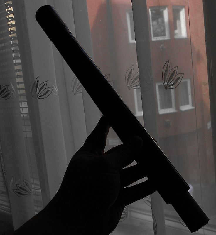
Our telescope, equipped with the Plossl eyepiece, offers significant magnification, making it impractical to use without proper support. To ensure easier aiming, it is recommended to mount the telescope on a camera tripod or to place it against a stable surface like a wall. Holding the telescope in your hands may be challenging, especially if you want to observe Jupiter’s satellites. However, with a tripod, you will have a much better chance of seeing them. Additionally, take a moment to admire the astonishing surface of the Moon!
For another fascinating experience, consider constructing a second telescope using acrylic lenses and observe the noticeable difference it brings.
Your telescope is a valuable tool for observing the stars, despite its smaller lens diameter compared to professional telescopes. While it may not collect as much light, it can still provide a magnification of 60-80x. To achieve a higher level of magnification, a lens with a diameter of 60-70 mm is needed, which may require a larger investment. However, with your 70-millimeter telescope, you have the ability to observe numerous celestial bodies that are otherwise invisible to the naked eye, including star clusters, bright galaxies, Saturn’s rings, the surface of Jupiter, and much more.
Interestingly, even Galileo’s most advanced telescope had limitations such as a smaller viewing angle and weaker optics compared to your own creation. Take pride in your accomplishments!
If you’re interested, I can guide you through the process of creating various objects with detailed step-by-step photo and video instructions.
Evtikhov, M. V. "Refractor telesmart" built from scratch / M. V. Evtikhov, D. I. Godunov. – Text : direct // Young scientist. – 2017. – № 3 (12). – P. 56-60. – URL: https://moluch.ru/young/archive/12/969/ (accessed: 18.08.2023).
This article discusses the development of an optical telescope integrated with a smartphone. The project was named “Telesmart”. The article provides a historical overview and basic concepts related to the operation of refractor telescopes, presents the design, and showcases the appearance of the created smart tele-hybrid.
The research relied on literature and online resources focusing on the design of refractor optical devices.
The gratitude of the author is expressed towards the leader of the project, D. I. Godunov, who is a physics teacher.
The electronic format of this piece of work can be found on the wikipedia project at: http://109.73.3.247:8080/wikiweb/index.php/Telesmart. The online version provides access to the most recent edition of the work and is open for discussion. There is also a support article with a “Discussion” tab for this purpose.
Any comments, suggestions, or questions can be directed to the author via email at [email protected].
Ancient opticians were familiar with the principle of light reflection, but they had limited knowledge about refraction and relied mainly on experimental data. In the 17th century, Snell and Descartes discovered the law of refraction, adding to the physical foundations of geometrical optics. These principles were fully understood and expressed elegantly in Fermat’s principle of the rapid passage of light rays during the first half of the 17th century. The practical significance of geometrical optics was further emphasized by Galileo’s trumpet and his groundbreaking astronomical discoveries. This transformed the field from a purely mathematical discipline into a vital and essential tool for the rational design and calculation of optical instruments [1].
In this study, similar to scientists from previous eras, an endeavor was made to invent a device that combines the telescope’s optical system with the optical and software components of a contemporary mobile device. To accomplish this objective, the following tasks were established:
2. To determine the optimal optical system configuration for the telescope, taking into consideration the smartphone’s optical system.
3. To materialize the calculation results by producing a functional prototype of the hybrid optical instrument.
Striving to enhance the telescope’s design in order to achieve the utmost image quality, the scientists developed multiple optical configurations utilizing both lenses and mirrors (refer to Figure 1).
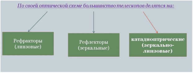
Figure 1. Optical configurations of telescopes
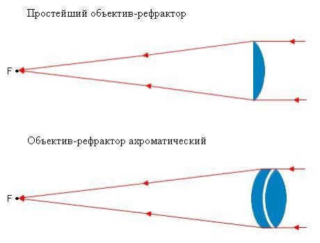
The optical system of a telescope The refractor telescope’s optical system is composed of individual lenses.
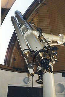
Externally, they can be easily identified: long narrow tubes, widened at one end where the objective lens is located. They do not require much adjustment, except for occasional sharpening [2]. Due to their limited light-gathering ability, they are not ideal for observing dim and hazy objects. However, they are well-suited for observing the Moon, planets, and binary stars. They can also be used as powerful telescopes for observing the surrounding environment (refer to Figure 2).
Telescope The primary tool used by astronomers to explore the Universe.
- Advantages and Disadvantages of Refractors
Refractor telescopes have several advantages compared to mirror reflectors. One advantage is that they bring a larger amount of collected light to the eyepiece, resulting in a clearer and brighter image. This increased permeability is due to the absence of a secondary mirror, which allows for a larger usable area of the lens. Additionally, the light in refractors directly enters the eyepiece without multiple reflections, resulting in improved contrast and clarity. Unlike mirror telescopes, refractors do not require frequent adjustments as all parts are rigidly fixed. Furthermore, their tight seal prevents dust accumulation, ensuring long-term functionality.
Drawbacks of Refractor Telescopes.
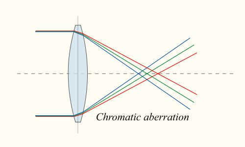
Firstly, there are various distortions associated with refractor telescopes, particularly chromatic aberrations or “chromatism”, which causes a colored glow to appear around objects. The brightness of the object determines the intensity of this glow. Chromatism becomes more pronounced with increasing lens diameter and shorter focal lengths. As a result, inexpensive achromatic telescopes, especially those with short focal lengths, are unable to achieve high magnifications.
The presence of chromatism is attributed to the fact that visible light consists of waves with different wavelengths or colors, which are refracted at different angles in the lens. Consequently, the image focus appears blurred along the optical axis [3].
3. Characteristics of optical telescopes
Choosing a telescope can be a challenging task. Some designs exhibit significant distortions in certain aspects, while others may have distortions in different areas. Additionally, models that minimize distortions tend to be more expensive, heavier, or have reduced luminosity. In certain situations, a larger aperture is necessary, such as when observing nebulae.
On the other hand, for observing the Moon, a higher magnification is often preferred. A smaller aperture (up to 70 mm) allows for viewing not only celestial objects but also terrestrial ones. The craters on the Moon can be observed clearly, and since the Moon is bright, the aperture size is less crucial. However, if higher magnifications are needed, a larger aperture and longer focus are required.
The most suitable system for observing galaxies (“dipskies”, deep sky) is the Newton reflector system, with an aperture of at least 150 mm. It becomes very challenging to observe dipscay with an aperture of less than 150mm.
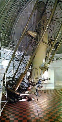
Figure 3 shows the locations and apertures of the most famous refractor telescopes.
The Yerkes Observatory in the USA is home to the largest refractor telescope in the world, which has a lens diameter of 102 cm. Larger refractors are not commonly used due to the high cost and weight of producing quality large lenses, which can lead to image deformation and deterioration. As a result, large telescopes are typically reflectors [4].
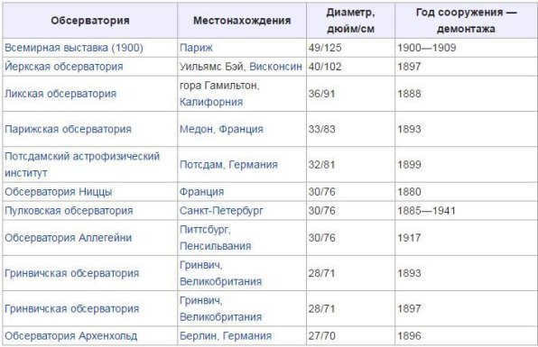
Figure 3. The biggest refracting telescopes
A unique combination of a smartphone and a telescope that is specifically engineered to capture and study celestial bodies such as stars, planets, their orbits, and the paths they follow within the solar system (refer to Figure 4).
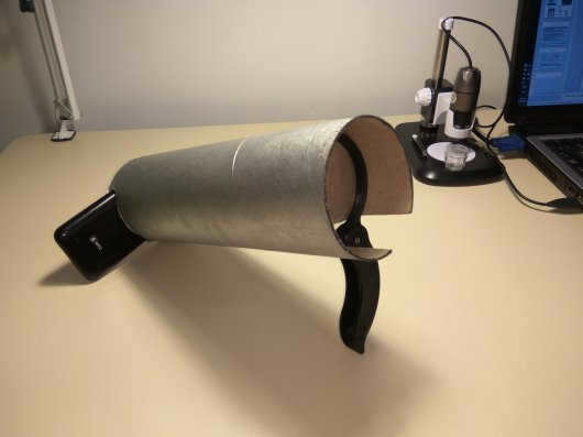
The telesmart can be easily constructed using readily available and simple components. It can be assembled by anyone using basic materials and tools. The main component is the tube, which can be made from sturdy paper or plastic of the appropriate diameter to hold the main lens securely.
This innovative device combines the functionality of a smartphone with a telescope, allowing users to capture and observe stars, planets, their orbits, and the paths of the planets in our solar system (refer to Figure 5).
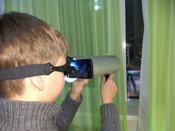
Figure 5. Telesmart in action
When combined with the popular software Stellarium [5] for mobile and personal computing devices, the telesmart being discussed becomes an impressive instrument for exploring the sky above us.
The telesmart’s operating model demonstrated satisfactory performance. The results obtained confirmed the feasibility of combining the optical systems of a telescope and a smartphone. However, as early as 1669, in his “Lectures on Optics,” Newton described the situation to his audience in these terms: “Those who study dioptrics believe that visual instruments can be perfected by using glass, if it is polished to achieve the desired geometric shape. Various tools were invented for grinding glasses into hyperbolic and parabolic shapes, but no one has been able to accurately produce such shapes so far, despite their efforts. Therefore, to avoid wasting further labor on a futile matter, I dare to caution that even if everything had succeeded, the results would not have met expectations. The glass, even with the best possible shapes that can be invented for it, would not perform twice as well as spherical mirrors polished with the same precision.”
The author is currently gathering material and performing calculations in order to create a functional model of a telesmart with a reflex system.
1. Vavilov S. I. Isaac Newton: 1643-1727.-4th ed., supplement.-M.: Nauka, 1989.- 271 p, ill. ISBN 5020000655
2. Refractor telescopes. [Electronic resource]. – Access mode: http://kosmoved.ru/refraktory.shtml.
3. A. Hendel – Basic Laws of Physics ed. by E. B. Kuznetsov // M. Fizmatgiz, 1963. – P. 312.
4. Refractor [Electronic resource]. – Access mode: https://ru.wikipedia.org/wiki/Рефрактор
5. Stellarium [Electronic resource]. – Access mode: http://stellarium.org/
Basic terminology (automatically generated): optical system of a telescope, telescope, geometric optics, solar system, smartphone hybrid, lens diameter, planetary trajectory, working model, aperture, Galilean, operation, sketch.
Related articles
Modeling motion of celestial bodies for scientific research.
The objective was to develop a software that can determine the positions of bodies moving in space by inertia (ballistically). These bodies can include planets, both natural and artificial satellites, the Sun, and other stars with their own planetary systems.
In the given illustration, the diagram titled “Schematic of the gravitational fields of the solar systems”
By having knowledge of the planets’ parameters such as masses, radii of their orbits, eccentricities, periods of motion, and velocities of the spacecraft, it is possible to compute the most efficient paths for the spacecraft’s motion.
The importance of the Kepler telescope’s mission in the exploration of exoplanets
The identification and analysis of exoplanets (derived from the Greek word ἔξω meaning “outside, beyond”) [5], which are planets located outside of our solar system, is a highly significant field of study in contemporary astronomy.
From the principles of kinematics established by Galileo and the laws formulated by Kepler to the laws of dynamics.
Out of all the planets in the solar system, only Mercury and Pluto exhibit noticeable deviations from the expected orbital patterns.
The satellite experiences a force, known as the centripetal force, acting on it from the central celestial body.
Observing the planet Saturn through a telescope reveals an intriguing and unique structure.
Estimate the distance to a observed object using a novel method.
This study introduces a groundbreaking algorithm for estimating the distance to an observed object based on stereo pair images. The significance of this research lies in its ability to accurately determine the distance to an object using images captured from two cameras, which is a crucial task in various fields.
The flight path of a robot in motion takes the shape of recurring cycles of movement. These cycles can be described by mathematical functions that have a limited number of variable parameters. This mathematical model enables the formation and optimization of the robot’s trajectory.
Autonomous orientation of an unmanned aerial vehicle within a system.
In order to address the challenges associated with monitoring territories and objects, both in military and civilian sectors, ultralight unmanned aerial vehicles are utilized. The key factor in ensuring successful task execution lies in the precise positioning of the vehicle.
Recognition of objects based on received video signals.
Many robotic systems require a sufficient amount of information about their surrounding environment. This information is used by the robot to determine its behavior. As a result, the robot is able to identify and track the structure of the objects in its surrounding area.
The importance of considering the surface effects of solar pressure and Earth’s thermal radiation on the spacecraft is discussed. The discussion revolves around the necessity of determining the spacecraft’s characteristic area more accurately and utilizing it accordingly.
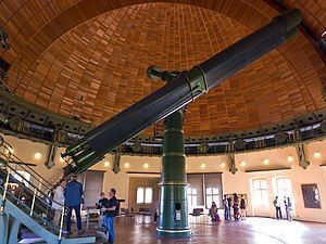
The Poznań Observatory houses a 200 mm refractor telescope. This type of telescope, also known as a refractor, utilizes a lens as its objective to produce an image. Originally developed for spyglasses and astronomical telescopes, refracting telescope design found its way into long-focus camera lenses as well. While large refracting telescopes were highly sought after during the latter part of the 19th century, reflecting telescopes have since taken their place for most research purposes due to their ability to accommodate larger apertures. To calculate the magnification of a refractor, one must divide the focal length of the objective lens by the focal length of the eyepiece.
Refractive telescopes typically feature a lens positioned at the front, followed by a lengthy tube, and then an eyepiece or other instruments located at the back where the telescope’s focus is directed. Originally, telescopes were equipped with single-element lenses, but as time progressed, two- and even three-element lenses were developed.
A refractive telescope is a technology that is commonly utilized in various other optical devices such as binoculars and zoom lenses / telephoto lens / long lens.
- 1 Invention
- 2 Designs of refractive telescopes
- 2.1 Galileo telescope
- 2.2 The Kepler telescope
- 2.3 Achromatic refractors
- 2.4 Apochromatic refractors
Refractors were the first kind of optical telescopes. The initial mention of a refracting telescope occurred in the Netherlands approximately in 1608, when a producer of eyeglasses named Hans Lippershey from Middelburg attempted to patent one, but without success. The news of the patent quickly spread, and Galileo Galilei, who happened to be in Venice in May 1609, learned about the innovation, built his own model, and used it to make astronomical breakthroughs.
Alternative configurations of refracting telescopes
All refracting telescopes operate on the same principles. They use a combination of an objective lens and an eyepiece to capture more light than the human eye can on its own. This captured light is then focused and presented as a brighter, clearer, and magnified virtual image to the viewer.
The lens in a refracting telescope refracts, or bends, light. This refraction causes parallel light rays to converge at the focal point, while non-parallel rays converge at the focal plane. The telescope takes a beam of parallel rays, which forms an angle α with the optical axis, and converts it into a second parallel beam with an angle β. The ratio of β to α is known as the angular magnification. It is equal to the ratio of the size of the retinal image obtained with the telescope to the size obtained without the telescope.
There are numerous arrangements available for refractive telescopes to correct image orientation and various types of aberrations. These telescopes are known as refracting telescopes or refractors because they form images through the bending of light or refraction.
The telescope of Galileo
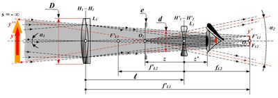
Optical diagram of Galileo’s telescope: y- Distant object; y’ – Real image from the objective lens; y” – Magnified virtual image from the eyepiece; D – Diameter of the entrance pupil; d – Diameter of the virtual exit pupil; L1 – Lens of the objective lens; L2 – Lens of the eyepiece; e – Virtual exit pupil – Telescope equals
The optical arrangement utilized by Galileo Galilei around 1609, commonly known as the Galileo telescope, consisted of a gathering (flat-convex) objective lens and a diverging (flat-curved) eyepiece lens (Galileo, 1610). This design, lacking an intermediate focus, produces a non-inverted and, with the assistance of certain devices, a direct image.
Galileo had a highly potent telescope that measured a total of 980 millimeters (3 feet 3 inches) in length and had the ability to magnify objects by approximately 30 times. However, this telescope had a couple of flaws in its design, including the shape of the lens and a narrow field of view, which resulted in blurry and distorted images. Nonetheless, despite these imperfections, Galileo was able to make significant astronomical discoveries using this telescope. He utilized it to examine the craters on the moon, observe the four largest moons of Jupiter, and study the phases of Venus.
When light rays from a distant object (y) are parallel, they can be focused at the focal plane of the objective lens (F ‘L1 / y’). The eyepiece (L2), which is diverging, intercepts these rays and makes them parallel again. The non-parallel light rays from the object, which come at an angle α1 to the optical axis, travel at a larger angle (α2>α1) after passing through the eyepiece. This leads to an increase in the apparent angular size and is responsible for the perceived magnification.
The finite image (y ″) is a virtual image located at infinity and is positioned upwards, just like the object.
The Kepler telescope
is an astronomical space observatory launched by NASA to discover Earth-sized planets orbiting other stars. It was named after the 17th-century German astronomer Johannes Kepler. The telescope was designed to monitor a specific region of the Milky Way galaxy for a period of four years. Its primary goal was to determine the frequency of Earth-sized planets in our galaxy and to estimate how many of these planets might be located in the habitable zone, where conditions could potentially support life as we know it. The Kepler telescope used the transit method to detect planets, which involved measuring the slight dimming of a star’s brightness as a planet passed in front of it. This method allowed scientists to identify thousands of exoplanets, including some that were similar in size and composition to Earth. The data collected by the Kepler telescope has greatly expanded our understanding of the diversity and prevalence of planets in our galaxy, and has paved the way for future missions to search for signs of life beyond our solar system.
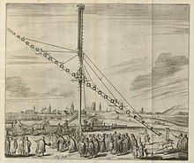
An engraved depiction of the Kepler Astronomical Refractor Telescope, constructed by Johannes Hevelius, measuring an impressive focal length of 46 m (150 ft).
The Kepler telescope, which was invented by Johannes Kepler in 1611, represents an enhancement of Galileo’s original design. Instead of using a concave lens like Galileo, Kepler’s telescope utilizes a convex lens as the eyepiece. This particular configuration offers the advantage of having converging rays of light exiting the eyepiece. As a result, the telescope provides a wider field of view and a greater exit pupil distance. However, there is a drawback to this design: the image observed through the telescope is inverted. Despite this, the Kepler telescope allows for significantly higher magnification, although a simple lens must have an extremely high f-ratio to correct for aberrations. In fact, Johannes Hevelius even constructed a lens with a focal length of 46 meters (150 feet), and there have been instances of even longer chamberless “air telescopes” being built. Additionally, this design permits the use of a micrometer in the focal plane in order to determine the angular size and/or distance between observed objects.
Huygens constructed a flying telescope for the Royal Society of London equipped with a 19 cm (7.5″) lens made from a single element.
Achromatic refractors
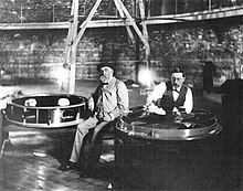 In 1896, Alvan Clarke polishes a large Yerkes achromatic refractor lens that measures over 1 meter in diameter.
 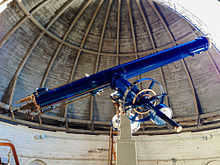 This refractor, measuring 12 inches, is installed in a dome and rotates in sync with the Earth’s rotation.
The achromatic lens, a key advancement in the development of refracting telescopes, was a breakthrough in addressing chromatic aberration and enabling shorter focal lengths. This lens, consisting of multiple elements, was first invented in 1733 by Chester Moore Hall, an English lawyer. Interestingly, it was independently invented and patented by John Dollond in 1758. By utilizing a combination of a “corona” and a “colorless glass,” the achromatic lens mitigated both chromatic and spherical aberration, eliminating the need for excessively long focal lengths. The lens is constructed by grinding and polishing each side of the two glass pieces before they are assembled together. Notably, the achromatic lenses are meticulously corrected so that the two wavelengths, typically red and blue, converge on the same focal plane.
Dollond’s achromats gained significant popularity during the 18th century due to their ability to be made in shorter lengths. However, the production of larger glass lenses was limited to a maximum diameter of four inches due to issues with glass making.
It wasn’t until the late 19th century when Guinand, a glass manufacturer, developed a method for creating higher quality glass blanks that exceeded four inches in diameter. He shared this groundbreaking technology with his apprentice Fraunhofer, who further refined the technique and also created Fraunhofer’s duplex lenses.
This advancement in glass manufacturing revolutionized telescope design, leading to the development of larger and more powerful refractors throughout the 19th century. By the end of the century, these telescopes reached sizes of over one meter. Eventually, they were superseded by silvered glass mirror telescopes in the field of astronomy.
Some notable lens makers of the 19th century include:
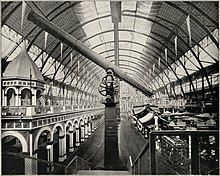
The 28-inch refractor at Greenwich, which has become a popular tourist attraction in London during the 21st century, was built by a number of renowned manufacturers including Elvan Clarke, Brashear, Chance Brothers, Koshua, Fraunhofer, Gauthier, Grubb, Henry Brothers, Lerebourg, and Tully.
Located at the Royal Observatory in Greenwich, a telescope known as the Shipshanks telescope, which was created in 1838, incorporates a Cauchois lens. This lens, measuring 6.7 inches (17 cm) wide, made the Shipshanks telescope the largest telescope at Greenwich for a period of approximately twenty years.
According to the Observatory’s report in 1840, the then-new Sheepshanks telescope with its Cauchoix doublet lens was highly regarded:
The power and quality of this telescope make it an extremely valuable addition to the Observatory’s collection of instruments.
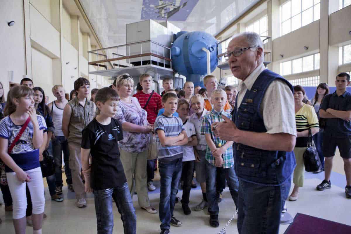
In the early 1900s, Zeiss emerged as a leading manufacturer of optical devices. One notable achievement in the field of refractors is the 12-inch Zeiss refractor at the Griffith Observatory, which has provided over 7 million individuals with the opportunity to observe since its establishment in 1935. This telescope holds the record for the largest number of people to have ever used a telescope.
Achromatic lenses were widely used in the field of astronomy for creating star catalogs, and they had the advantage of requiring less maintenance compared to metal mirrors. Some notable astronomical discoveries made using achromatic lenses include the identification of the planet Neptune and the observation of the moons of Mars.
Despite their smaller aperture when compared to larger reflecting telescopes, long achromatic lenses were often the preferred choice for prestigious observatories. During the late 18th century, it became a common occurrence for a larger and longer refracting telescope to be introduced every few years.
For instance, the Nice Observatory made its debut with a refractor measuring 77 centimeters (30.31 inches) in aperture, which was considered the largest at the time. However, this record was quickly surpassed within just a couple of years.
Apochromatic refractors
Apochromatic lenses are typically composed of three elements that focus light of three different frequencies into a single point.
Apochromatic refractors utilize lenses crafted from specialized materials with extremely low dispersion. These lenses are designed to focus three specific wavelengths (typically red, green, and blue) onto the same plane. The residual color error, or tertiary spectrum, in these refractors is significantly smaller compared to that of achromatic lenses. These telescopes incorporate elements made from fluorite or special ultra-low dispersion (ED) glass in their objective lenses, resulting in exceptionally sharp images with virtually no chromatic aberration. Due to the unique materials used in their construction, apochromatic refractors tend to be more expensive than other telescopes of similar aperture size.
One of the renowned sets of three lenses is the Cooke triplet. This particular design is well-known for its capacity to rectify Seidal aberrations. It has gained recognition as one of the most crucial objective designs in the field of photography. The Cooke triplet is capable of correcting spherical aberration, coma, astigmatism, field curvature, and distortion with just three elements for a single wavelength.
Considerations from a technical standpoint
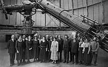
The Yerkes Observatory houses the largest achromatic refractor ever utilized in astronomy, measuring 102 centimeters (40 inches) in diameter (photographed on May 6, 1921, during Einstein’s visit).
Chromatic and spherical aberration are known issues with refractors. These aberrations are more noticeable in refractors with shorter focal ratios. For instance, a 100 mm (4 inch) f/6 achromatic refractor is likely to exhibit significant color fringing, often resulting in a purple halo around bright objects. Conversely, a 100 mm (4 inch) f/16 refractor experiences minimal color fringing.
When the aperture of a lens is very large, there is an issue of lens sagging caused by the gravitational deformation of the glass. The center of the lens sags due to gravity since it can only be held in place by the edge, which leads to distortion in the resulting images. The largest practical size for a lens in a refracting telescope is around 1 meter (39 inches).
Another problem arises from defects in the glass, such as grooves or small air bubbles trapped within. Moreover, certain wavelengths are obstructed by the opacity of glass, and even visible light is affected by reflection and absorption as it passes through the glass and crosses air-glass interfaces. Reflecting telescopes, which can have much larger apertures, are being increasingly used in astronomical research as they eliminate or reduce most of these issues associated with refractors.
Applications and achievements
 In 1904, the Große Refraktor twin telescope, equipped with lenses measuring 80 cm (31.5″) and 50 cm (19.5″), made the groundbreaking discovery of calcium as an interstellar medium.
 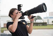 Astronauts are trained to use cameras with large lenses.
Refractor telescopes have long been recognized for their contributions to astronomy and their ability to observe the Earth. Many important findings about the solar system were made using single lens refractors.
The use of refractive telescope optics is widespread in photography and in Earth’s orbit.
Galileo made one of the most well-known applications of the refractor telescope in the field of astronomy. It was in 1609 when he utilized this instrument to uncover Jupiter’s four largest satellites. Moreover, several decades later, early refractors were employed to detect Titan, the largest moon of Saturn, along with three other moons of the same planet.
In the 1800s, refracting telescopes played a crucial role in advancing astrophotography and spectroscopy. Additionally, the heliometer, a related instrument, was utilized for the first time to determine the distance to a distant star. However, due to their limited apertures, refracting telescopes were unable to make as many discoveries as their reflecting counterparts. It was not until the introduction of long exposure photography that the reputation and capabilities of reflecting telescopes began to overshadow those of refractors, allowing astronomers to observe previously inaccessible astronomical objects. Nonetheless, refractors did contribute to significant findings such as the identification of Mars’ moons, the discovery of Jupiter’s fifth moon, and numerous double stars including Sirius (also known as the Dog star). Moreover, refractors were frequently employed in positional astronomy, as well as other applications in photography and Earth observation.
Using single-element lenses and airborne telescopes, Galileo Galilei and numerous other satellites of the solar system were first observed.
In 1610, Galileo Galilei used a refracting telescope to discover the Galilean satellites of Jupiter.
Titan, a moon of Saturn, was discovered on March 25, 1655, by the Dutch astronomer Christiaan Huygens.
In 1861, the smaller companion of the brightest star in the night sky, Sirius, was discovered using an 18 and a half inch Dearborn refractor telescope.
Deimos was discovered by Asaph Hall on August 12, 1877, around 07:48 UTC, while Phobos was discovered on August 18, 1877, at the U.S. Naval Observatory in Washington, D.C., around 09:14 GMT. According to contemporary sources, using the pre-1925 astronomical convention, the discovery times are given as August 11, 14:40, and August 17, 16:06 Washington Mean Time, respectively.
The discovery was made using a 26-inch (66 cm) refractor telescope, which was located in Foggy Bottom at that time. The telescope’s lens was reinstalled in 1893 and placed in a new dome, where it has remained to this day in the 21st century.
Edward Emerson Barnard discovered Jupiter’s moon Amalthea on September 9, 1892, using a 36-inch (91 cm) refractor telescope at Lick Observatory. The discovery was made through direct visual observation with a double-lens refractor.
In 1904, the Potsdam Great Refractor (a telescope with two doublets) made a significant discovery – the existence of the interstellar medium. Prof. Hartmann, an astronomer, established this fact by studying the double star Mintaka in Orion and determining that the interstellar medium contained calcium.
The planet Pluto was first spotted through the use of photographs, known as “plates” in the field of astronomy. These photographs were viewed in a blinking comparator, which was equipped with a refracting telescope – an astrograph that featured a 3-element, 13-inch lens.
List of the largest refracting telescopes
 The Yerkes Great refractor was installed at the 1893 World’s Fair in Chicago and was the tallest, longest, and largest aperture refractor at that time.
 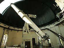 There is also the 68 cm (27 in) refractor located at the University of Vienna Observatory.
Here are some examples of the largest achromatic refractor telescopes that have a diameter of over 60 cm (24 in).
- The Large telescope of the 1900 Paris Exposition had a diameter of 1.25 meters (49 inches) but was dismantled after the exhibition.
- The Yerkes Observatory has a diameter of 101.6 cm (40 inches).
- The Swedish 1st solar telescope has a diameter of 98 cm (39 inches).
- The Lick Observatory has a diameter of 91 cm (36 inches).
- The Paris ObservatoryMethodon Great Refractor has a diameter of 83 cm (33 inches) and an additional 62 cm (24 inches).
- Potsdam Great Refractor (80 cm or 31 inches, plus 50 cm or 20 inches)
- Nice Observatory (77 cm or 30 inches)
- John Wall (76.20 cm or 30 inches) dialite refractor telescope, the largest refractor ever constructed by humans at Hanwell Community Observatory
- Grubb’s 28-inch refractor at the Royal Greenwich Observatory, with an aperture lens of 71 cm or 28 inches
- Great Refractor of the Vienna Observatory, measuring 69 centimeters or 27 inches
- Archenhold Observatory, holding the record for the longest refractor telescope ever built, with a focal length of 68 cm or 27 inches and a length of 21 meters or 69 feet
- Refractor at the U.S. Naval Observatory, measuring 66 centimeters or 26 inches
- Newall refractor at the National Observatory of Athens, with a diameter of 62.5 cm or 24.6 inches
- Lowell Observatory, with a diameter of 61 centimeters or 24 inches