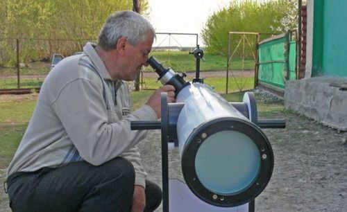
Looking to purchase a refractor telescope with a lens in Petrozavodsk?
Our team of experts is here to assist you in selecting the finest lenticular refractor telescopes available.
We are also able to provide you with the most current information regarding availability, payment options, and delivery terms for customers in Petrozavodsk.
Swift delivery
Convenient payment options
100% assurance
Refractors – lenticular telescopes
All telescopes are divided into two main categories based on the type of lens they use: refractors and reflectors.
Refractor – a telescope that employs an optical lens as its objective lens, whereas a reflector employs an optical mirror as its objective lens.
Both designs possess their own advantages and disadvantages. Nevertheless, both have been in operation for centuries.
Their drawbacks are counteracted by cutting-edge technology, enabling both types to be applied in various ways.
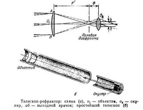
The primary configurations of refracting telescopes
The initial, most basic design of a telescope was proposed, supposedly by Galileo. It employed a converging lens as the objective and a diverging lens as the eyepiece. This resulted in a non-reversed depiction of the subject.
Drawbacks of Galileo’s design:
- Relatively dim image;
- Considerable optical distortions;
- Lack of an intermediary image for placing a measuring grid.
This configuration is still utilized today, but primarily in situations where an accurate non-reversed view of the subject is crucial.
Another configuration utilizing two converging lenses was devised by Kepler.
In this system, there exists a real image between the objective and eyepiece lenses where a measuring grid can be positioned.
Moreover, the length of the tube is determined by adding the focal lengths of the lenses, instead of subtracting them as in Galileo’s design, thus resulting in an increase in the tube length.
Drawbacks of Kepler’s design:
Kepler’s design enables much wider angles of field of view compared to Galileo’s design.
Receive expert advice directly to your Email
Our team is here to provide you with guidance on the top models of refractor lenticular telescopes in Petrozavodsk.
With the assistance of a prism turning system, the inverted image produced in Kepler’s tubes can be restored to its original orientation.
This is particularly useful in situations where a real image needs to be observed, despite the additional distortions and decrease in light intensity that may occur.
Therefore, inverted images are commonly utilized in astronomical lenticular telescopes.
Overall, Kepler’s system offers more advantages compared to Galileo’s design, making it widely adopted not only in telescopes, but also in observation tubes, high-magnification binoculars, and various other optical instruments.
Refractors are telescopes that use lenses.
Reflectors are telescopes that use mirrors.
Catadioptrics are telescopes that use a combination of mirrors and lenses.
Receive a telescope blacklist in your email.
We will provide you with a list of refracting telescopes that are not recommended for purchase.
Drawbacks of Refracting Telescopes
Refracting telescopes, also known as lensed telescopes, have several disadvantages compared to their reflector counterparts. These drawbacks arise from the inherent physical properties of lenses:
- Chromatic aberration
- Spherical aberration
- Inability to adjust the optical parameters of the lens
- Relatively long tube length
Fortunately, modern lens manufacturing methods, advancements in optical glass properties, and precise manufacturing technologies for telescope components have made it possible to mitigate many of these disadvantages. Spherical aberrations, for example, can be minimized through precise control of the lenses’ geometric parameters.
Special achromatic lenses are utilized in order to minimize chromatic aberration. These lenses are composed of multiple materials with varying dispersion, which aids in offsetting the underlying cause of chromatic aberration – the divergent angles of rays based on their wavelengths.
The Benefits of Refractor Telescopes
With the introduction of competitors like reflector telescopes, there was initially speculation that they may eventually replace optical instruments entirely in the field of astronomy.
Reflectors do offer advantages such as the ability to reflect light with less distortion, minimal chromatic aberration, and the ability to adjust the curvature of the mirror, giving them a strong alternative design.
However, it became apparent that reflectors also have their drawbacks. Optical devices are much more reliable and less temperamental.
Furthermore, producing a mirror surface without microscopic imperfections remains a difficult task even today.
There are numerous individuals who lack knowledge about optical telescopes, which makes it difficult for them to select the right ones and understand classifications and schemes. Furthermore, astronomy enthusiasts will undoubtedly be delighted to learn about the purpose of telescopes and the inventors behind the first models. Additionally, it would be beneficial for them to be aware of the largest optical telescopes in the world.
Overview
Optical telescopes are specialized instruments that gather and concentrate visible electromagnetic waves. Their primary function is to amplify the brightness and apparent size of astronomical objects. From a physics perspective, the objective of these devices is to enhance the amount of light received from celestial bodies, commonly referred to as optical penetration.
Amateurs are more acquainted with another application of telescopes – the examination of intricate features of celestial bodies through improved resolution.
It is worth noting that these devices serve not only for direct personal observation of space, but also for photography. In fact, for professionals, photography is the main focus, and the study of the images obtained by the system comes after. The key features of telescopes include:
The operation principle of telescopes is directly linked to their structure. They contain a system of lenses or mirrors. Telescopes with a single optical glass have long been outdated. When an astronomer uses a telescope, they adjust the parameters of the eyepiece while keeping the lens unchanged. This allows for changes in magnification. The device includes both collecting and diffusing lenses, and the clarity and accuracy of the picture depend on the correct selection and use of these lenses.
Sometimes there is a claim that Galileo was the original developer of the telescope. However, this claim is false. The true inventor remains unknown and it is highly unlikely that their identity will ever be definitively established. It is widely believed that the pivotal breakthrough was made by John Lippersgei, a skilled maker of eyeglasses. However, it is probable that the invention of the telescope occurred simultaneously in multiple locations, as the need for such a device was acutely felt at the start of the 17th century.
This information is indirectly confirmed and well-known. When filing for a patent, it was discovered that multiple devices of the same type had already been registered. There is a belief that Leonardo da Vinci created the prototype of the telescope. Galileo’s contribution was in developing the reflector telescope and managing to increase the magnification from 3 to 32 times in a few models.
Today, even amateur astronomers would consider these figures low. However, Galileo’s telescopes allowed for several important discoveries, such as identifying stars in the Milky Way and observing sunspots. Interestingly, the term “telescope” itself did not appear until 1611, and it was coined by the Greek mathematician Dimisianos.
Isaac Newton played a significant role in the advancement of telescopes with his development of the reflector, a component that enhanced the tube’s characteristics and allowed for better control.
During the 17th and 18th centuries, refractor telescopes continued to be widely used. This was mainly because reflectors were expensive and complex. In the mid-19th century, mirrors with silvered glass were introduced. In the last century, a major innovation was the widespread use of large mirrors. The creation of these mirrors would not have been possible without the development of a strong industrial base.
Types of Telescopes
Refractor
Refractor telescopes, also known as lensed telescopes, utilize multiple lenses to mitigate the individual optical disadvantages of each lens. This design recognizes the significance of the focal length, which determines the size of distant objects in the focal plane. Each telescope is equipped with a variety of eyepieces suitable for different situations. Furthermore, there are specialized refractor telescopes, known as astrographs, that are specifically designed for photography.
This particular kind of telescope is known as a reflector, which is also referred to as a mirror telescope. The mirror used in this type of telescope is simpler to manufacture and has a concave parabolic shape with a relatively small curvature. To enhance its reflective properties, a small amount of powdered aluminum is applied to its surface.
Utilizing a mirror in its construction enables this telescope to effectively observe intricate details of celestial objects within our local space, such as planets, their satellites, and even rings. Reflectors are well-suited for studying nebulae, comets, and other expansive objects in the universe. However, there are also telescopes that incorporate a combination of mirrors and lenses, resulting in a more compact design.
These compact models are commonly used for domestic purposes, although they suffer from significant light loss, which complicates their performance. Additionally, a high-quality mirror-lens system can be quite expensive.
Overview of the biggest telescopes in the world
The size of a telescope is determined by the size of its optical components. The largest ones are strategically placed in areas with optimal atmospheric conditions for observing space. Leading the list of the biggest instruments in the southern hemisphere is SALT, situated in a semi-desert region of South Africa. Its primary mirror alone measures 11×9.8 meters. It has been actively used for practical observations since 2005, equipped with a dedicated digital camera and a versatile spectrograph.
The GTC, also known as the Great Canary Telescope, is one of the modern telescopes. It has been in operation since 2007 and is capable of both optical and infrared observations. With a mirror size of 10.4 m, it utilizes a variety of additional instruments.
The European Extremely Large Telescope (E-ELT) is set to be the largest telescope of its kind. Although it is not yet operational, it is expected to begin operations in 2024. The main segment mirror of the E-ELT measures a whopping 39.3 meters. Situated on Mount Armasones in Chile, at an altitude of over 3 km above sea level, it is poised to revolutionize astronomical research.
The biggest telescope in Russia is known as the “Big Azimuthal Telescope” which can be found near the village of Nizhny Arkhyz. The mirror’s diameter is no more than 6 meters. It is important to note that the positioning of the telescope is considered to be unfavorable, so the most efficient observations cannot be guaranteed.
However, it is still possible to observe stars up to the 26th magnitude. Moreover, this telescope is also capable of conducting spectroscopy effectively.
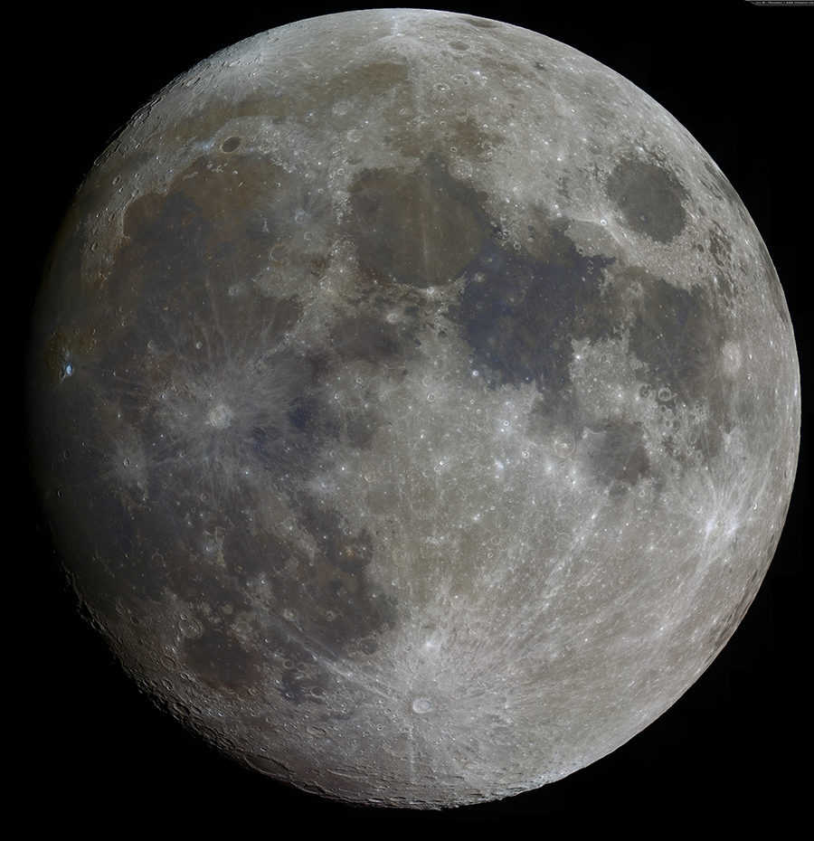
The refractor telescope is a classic option, resembling the traditional “telescope on legs”. If you are interested in observing bright objects like the Moon or double stars, the refractor scheme is the optimal choice. It is also suitable for daytime observations. However, it is not suitable for viewing distant faintly luminous objects. This drawback compromises both high contrast and ease of maintenance.
The previously mentioned reflectors can be categorized into two groups: a simple subgroup and a more expensive one. In the latter case, a parabolic mirror is used. Despite comparable costs, a reflector has a larger lens cross-section compared to a refractor. As a result, it offers better optical performance and light concentration. Reflectors are recommended for observing objects beyond the solar system.
However, reflector telescopes are heavier than refractor telescopes. They require observing at a specific angle, which can be challenging for inexperienced astronomers. Catadioptrics are an intermediate option that combines features of both types. They do not require regular maintenance.
However, the image has a low contrast, while the price, on the other hand, is quite considerable.
Nevertheless, it is not logical to confine ourselves to the mentioned circumstances. The size of the lens opening, also known as the aperture, is the main factor that determines the capabilities of the telescope. The ability to show small details of objects can be judged by this parameter. The concentration of light is much more important than the level of magnification. Increasing the size of the aperture is much simpler than using a larger mirror, and for individual users, this option is more convenient and compact.
Excessive magnification is not always beneficial. Furthermore, it not only has negative effects on other telescope parameters, but it can also increase sensitivity to vibrations and susceptibility to atmospheric distortions. The installation type distinguishes azimuthal and equatorial telescopes. Azimuthal telescopes rotate on two axes, while equatorial telescopes rotate on only one axis, making them more practical.
No matter what type of setup you have, it is crucial to assess the stability of the instrument to determine if small vibrations can have a detrimental impact.
Welcome to our astronomy forum!
We are glad to have you here and we are confident that you will find intelligent answers to your questions on amateur astronomy. Our community is built on experience and knowledge, not on guesses, myths, or skimming through the Internet.
If you choose to become a member, we kindly ask you to abide by these rules in your responses as well.
Areas of Focus: Frequently Asked Questions (FAQs), Equipment Reviews, and Eyepieces
How to modify a refractor
Ernest Founder Messages: 17037 Posted: October 12, 2009, 10:55 pm. Contact info:
How to adjust the alignment of a refractor
Message from Ernest ” 03 Mar 2015, 00:27
Aligning the stars with a refractor
Most modern refractors with good quality have an adjustable frame that allows each lens to be shifted slightly using three or four set screws made of metal or polyethylene. These screws, usually M4 in size, are hidden inside threaded holes on the side surface of the frame and can be adjusted using a straight slot or hexagon screwdriver. When a lens is shifted, it moves along the contact surface with the other lens. This contact surface is typically set by three point spacers around the perimeter of one lens or a thin spacer ring between the lenses. If a lens becomes misaligned, this displacement between lenses can cause image shift and the appearance of decentration aberrations such as coma and/or transverse chromatism along the image axis. On the other hand, if a lens is intentionally shifted to compensate for misalignment, it can introduce an equal but opposite decentration aberration, effectively nullifying the original aberration.
- Observe the star by magnifying it at high power (1.5-2D) using a telescope with a 100 mm refractor.
- Check for any signs of coma: if there is no noticeable variation in brightness around the central core of the image, then there is no coma. However, if there is a significant amount of coma, you will see a distinct fan-shaped aberration with a bright apex and a dimmer 60-degree sector forming a “tail”. In milder cases, you may only observe a brightening on one side of the first diffraction ring (the remnants of the tail). If no coma is detected, stop the alignment process.
- Determine the magnitude and direction of the comet’s tail.
- Select the appropriate direction (as shown in the second figure) and adjust the alignment slider (either by turning the screws or rotating the slider) to the desired size.
- To initiate the movement, loosen one or two adjustment screws to create space for the movement. Then, tighten one or two screws to select it and shift the chosen lens along the axis.
- Return to the second step and repeat our attempts to calibrate the telescope.
In each of the six sections, I have combined the star image at the center of the eyepiece’s field of view (with a noticeably exaggerated coma effect) and the refractor frame (as observed from behind, through the focuser) with three alignment screws: align the top of the frame with the top of the field of view, the right side of the frame with the right side of the field of view, and so on.
How should these nomograms be used?
Let’s take a look at the initial one (letter A): the comma that we have detected in the middle of the field of view points downwards (towards the observer’s abdomen) and upwards (towards the objective end of the tube). In case we have chosen a positive lens for the adjustment (marked with the “+” sign), we need to move the adjustment screws in the directions indicated by the “+” signs: start by unscrewing the right and left screws, and then screw in the upper adjustment screw on the frame. If a negative (scattering) lens is chosen for adjustment, then while turning the adjustment screws on the frame, follow the directions of the arrows labeled with “-“: unscrew the upper screw, and screw in the right and left screws.
The same applies to other orientations of the comma. For instance, the comma appears with the top facing right (and the fan facing left) – as shown in the second picture in the second row (letter E). Keep the upper screw fixed, and only adjust the right and left screws: when adjusting for a negative lens, slightly unscrew (loosen) the right screw and screw in the left screw (to fill the gap created by the right screw). Conversely, for a positive lens, do the opposite.
A few important points to consider:
- Don’t forget that before tightening the adjustment screw(s), you should loosen one or two opposing screws, meaning that at each adjustment step, first unscrew and then screw in;
- Avoid over-tightening the screws – if you encounter significant resistance, stop;
- If the aberration pattern has deviated from coma (such as astigmatism or incorrect diffraction rays), it could be due to over-tightening – simply loosen the most recently tightened screw and continue in a circular pattern until the distortions change back to the typical coma;
- If it is not possible to achieve the required movement and the screw is stuck, and the coma persists, it indicates that the adjustment gap in the frame has been chosen incorrectly and it is best to leave this lens alone and move on to another one.
- Exercise caution when dealing with polyethylene screw slots – excessive force or incomplete insertion of the screwdriver can result in easy tearing.
- After completing the alignment, choose the appropriate clearances – gradually tighten all screws in a circular motion until they lightly touch the glass. Take care to avoid disrupting the achieved alignment. Verify the appearance of the star image. It is advisable to rotate the tube in the rings by 180 degrees to ensure that the lenses are securely held in place and to prevent excessive coma, which may not be completely eliminated across the telescope’s temperature range.
- If you are aligning without a diagonal, adhere to the following guideline: apply pressure to the negative lens with the alignment screw from the tail side of the coma in order to eliminate it, and do the same for the positive lens from the top side. However, if you are aligning with a prism of direct vision (with a “roof”), the procedure is reversed: in order to eliminate coma manifestations, exert pressure on the negative lens with the alignment screw from the side of the apex (brighter part) of the aberration spot, and for the positive lens – from the side of its tail.
- Once you have adjusted your refractor for coma, it is important to also check whether you have inadvertently adjusted the transverse chromatism of magnification. This can be identified by observing the star’s image stretching in the spectrum, with a reddish side on one end and a bluish side on the other. To detect this transverse chromatism, UHC filters are particularly effective: they cause the star’s image to split into a bright blue section and a dim red section. In cases where the refractor has two lenses, this may indicate that the air gap between the lenses has a wedge shape, and it cannot be resolved without disassembling the lenses and adjusting the thickness of spacers around the perimeter. However, for refractors with three lenses and a greater degree of freedom, it is possible to minimize the transverse chromaticity by readjusting the middle (positive) component with careful selection of the shift.
Ernest Founder Posts: 17037 Posted on: October 12, 2009, 10:55 pm. Contact info:
TAL100R lens alignment history
Message Ernest " 02 Oct 2016, 15:45
TAL100R lens alignment
I recently obtained a TAL100R tube that was suspected by the owner to have coma in the center of the field of view. He asked for my assistance in resolving this issue. Even a cursory examination confirmed the presence of a noticeable coma in the center of the field of view. My estimation is that it is approximately 1/3 of a wavelength, as shown in the figure:
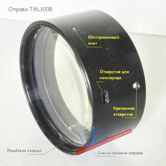
Schematic diagram of lens placement in the frame
Prior to alignment, it was necessary to (1) eliminate the substance that restricted the movement of the front lens component, (2) comprehend the lens basing scheme, as errors in this scheme could result in the aforementioned coma, and only then develop approaches to alignment. The first task turned out to be quite simple – the sealant was soft and easy to remove, and there wasn’t much of it.
And here is my reconstruction of the lens basing scheme for the TAL100R.
The lens is inserted into the frame from the outside (the side where the light enters during operation), starting with the second lens.
The fundamental (second-to-light) principle of the negative lens
The second lens is placed on a circular belt within the frame, which has a flatter rear surface. This belt restricts the lens from moving along the optical axis and tilting in two perpendicular directions, thus reducing its degrees of freedom. If the base is misaligned with the tube/rim axis or if there is a poor fit due to a burr or debris, the lens axis will tilt in relation to the tube axis, resulting in the appearance of astigmatism along the axis. The severity of the astigmatism increases with a greater tilt of the lens. This relationship is quadratic, meaning that small errors are tolerable, but beyond a certain threshold, the manifestations of astigmatism become more pronounced. In traditional refractors, three adjustment screws were used to correct for this error by tilting the entire lens relative to the tube axis. However, this lens does not have such a mechanism, as the manufacturer relies on the precision of the mechanical bases within acceptable tolerances.
By placing the second lens inside the frame cylinder, two additional mechanical degrees of freedom (displacements in two perpendicular directions) are eliminated. The lens is pre-centered to ensure that its lateral cylindrical surface is aligned with its optical axis, which is the line connecting the centers of curvature of the two working surfaces. However, any errors in this centering process or play in the lens fit can result in residual astigmatism in the center of the field of vision. The manufacturer relies on maintaining tolerances to prevent the occurrence of astigmatism for both themselves and the instrument’s owner.
Once the negative lens has been fitted (and its position on the collimator possibly checked), it is secured to the frame using glue.
Air gap between the lenses
The specifications of the air gap between the lenses (including centering and designated thickness) are typically ensured by a thin metal (or sometimes plastic) ring placed between the lenses. Some manufacturers cut costs by substituting this ring with three separate supports positioned between the lenses at the outer edge (beyond the area of light transmission). Unfortunately, in the TAL100R model, the manufacturer has opted for this less reliable approach. The supports must be securely attached (usually with adhesive) at precisely the same distance from the lens axis and possess exactly the same thickness (taking into account possible imperfections, adhesive layers, and deformations). These requirements are rather challenging to achieve with separate supports (as opposed to a ring component). Errors in the positioning of the supports, their thickness, and variations in the thickness of the adhesive layer used to affix them to the lens can result in the occurrence of coma at the center of the image and the manifestation of spherical aberration.
Home adaptation
Upon analyzing the arrangement pattern, a specific area of interest was identified – the space between the lenses. To address the issue of a wedge-shaped air gap causing coma in the center of the field of view, adjustments need to be made to the position and thickness of the three spacers located between the lenses. These spacers, made from lightweight aluminum measuring 0.35 mm in thickness and 5×1.5 mm in size, were poorly crafted with irregular shapes and burrs on both the front and back sides. During the removal of the spacers from the diffusing lens, one of them unexpectedly split into two, possibly suggesting that this duality was the root cause of the coma. Although I initially overlooked this possibility, I proceeded to carefully sharpen the spacers using fine emery cloth (a challenging task due to their small size), verified their thickness with a micrometer, and securely bonded them to the positive lens using cyanoacrylate glue at 120-degree intervals along the perimeter. This approach was adopted as the negative lens proved impossible to remove from the frame.
How to manage the wedge-shaped gap between the lenses
Our next task was to find a convenient method for checking the wedging of the air gap. Testing the gap after each adjustment in fitting the spacers to a natural or artificial star would have significantly slowed down the alignment process. The GMK collimator proved to be too coarse of an instrument, as it did not show the double glare from the adjacent lens surfaces. Even when illuminated by a coherent source, the picture of Newton’s rings was not clear. I attempted to use a laser collimator, but the reflection spot from the surfaces of the air meniscus that I was interested in was too large, making it impossible to achieve the desired wedge shape. However, I discovered something interesting – within this large reflected spot, I could clearly see a striped structure. It was the result of interference caused by the difference in the paths of rays reflected from the surfaces of the air meniscus. After several attempts, I devised the following testing method: I placed the lens (outside the tube) on the floor and directed a vertical laser beam (green pointer) into the lens. The most interesting phenomena occurred on the ceiling – in addition to two compact and bright glares from the front and back surfaces of the lens, a rather large striped spot appeared. This spot was the result of the interference of light reflected from the surfaces of the air meniscus between the lenses. It intersected a portion of the interference pattern with Newton’s rings. By scanning the entire area of the lens with the laser beam, I was able to see the complete Newtonian pattern, including its central part. In the general case (when the desired wedge-shaped air gap was present), the central part was displaced from the lens axis. Using the laser beam, I located this position on the lens where the interference fringes disappeared in the described spot. This indicated that the laser beam had entered the “dead zone” – the center of Newton’s rings, and therefore indicated the actual top of the air gap.
Adjusting the spacing
Initially, the center of the air meniscus was moved to the outer edge of the lens. I marked this point and made adjustments to the thickness of the spacers there to raise the front lens at that edge (or alternatively, lower it slightly at the opposite edge). To decrease the thickness, I scraped metal from the spacers, and to increase it, I added a piece of thin tape. After approximately 5-6 attempts, the center of the Newton rings gradually moved towards the optical axis of the lens. This process was quite painstaking – during each iteration, I had to position the lens (without screwing it in with the threaded ring or securing it with alignment screws), move the lens to the floor near the wall (which served as a base for the laser pointer on the stand), observe the striped glare from the laser pointer on the ceiling, locate the position of the laser beam on the lens where the glare shifted to the center of the Newton’s ring pattern, mark this position, and then return the lens to the work table for further adjustments to the spacer thicknesses.
Washing and assembly
While performing the aforementioned tinkering, I inadvertently soiled the front lens – it necessitated a cleansing with alcohol upon completion of the process. Subsequent to the washing, the lens barrel was reinserted into the telescope tube.
Correcting transverse chromatism
Next, the transverse position of the front lens was adjusted using the alignment screws. I have already done this using the star image (Polar) – we had a few clear nights. Initially, the threaded ring is loosened by half a turn, and the screws are almost not in contact with the side surface of the lens. By tapping on the tube, I ensure that the lens settles on the gasket supports (the tube is pointed steeply upwards towards Polaris). Through the eyepiece at 225x magnification, I observe the image of Polar with a diffraction pattern, but unfortunately, it is affected by transverse chromatism – red and blue halos dispersed in different directions from the central image. The red side in the star image indicates the direction in which the star image needs to be shifted along the field of view using the alignment screws to adjust the lens. Through small tests, I search for a combination of screws that can achieve this displacement of the star image. Once I find the right screw(s), I begin to gradually move the lens while observing the changes in the star image. If there are signs of coma, it means that the lens has lost contact with one of the supports. In this case, I need to loosen the screws that prevent the free movement of the lens (on the opposite side from the screw(s) used for alignment displacement) and tap on the tube to settle the lens again on the gaskets. Using this method, I successfully achieved axisymmetry of the colored halo (without multicolored “ears”). The result is a chromatic Eiri picture with an enhanced brightness of the first diffraction ring and a slightly blurred blue-red halo.
Summary and suggestions
I found the process of adjusting the TAL100R fascinating, like solving a puzzle, and it reaffirmed my passion for overcoming challenges. After several days of searching and struggling, I discovered and applied a method for aligning the telescope, resulting in improved image quality. Fine details of observed objects became more visible and distinct at higher magnifications. The ability to see distant objects may have also slightly improved, although the Polar satellite remained equally visible both before and after the alignment.
The era when anyone could make a scientific discovery is mostly a thing of the past. All the knowledge and calculations in the fields of chemistry, physics, and biology that could be discovered by amateurs have already been documented and studied extensively. However, astronomy stands as an exception to this trend. As the study of space, it encompasses an unimaginably vast realm where countless mysteries still remain unsolved. Even in the vicinity of Earth, there are objects yet to be discovered. Nevertheless, pursuing astronomy requires the use of a telescope, which can be a costly optical instrument. Is constructing a homemade telescope a simple or complex undertaking?
Can Binoculars Be Useful?
For a beginner astronomer who is just starting to explore the night sky, building their own telescope may seem like a daunting task. The process might appear too complex for them at this stage. However, they can start with something simpler – regular binoculars.
Binoculars are not as trivial as they may seem, and there are even renowned astronomers who continue to use them. For instance, the Japanese astronomer Hiyakutake, who discovered the comet named after him, gained fame for his preference for using powerful binoculars.
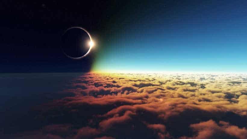
When starting out as a beginner astronomer, it is important to determine if it is “your thing” or not. Any high-quality marine binoculars can be used for this purpose. The larger the lens diameter, the better the observation experience. Binoculars allow you to view the Moon in impressive detail and see the disks of nearby planets like Venus, Mars, and Jupiter. They also provide the opportunity to observe comets and double stars.
No, a telescope!
If you have a genuine passion for astronomy and are keen on building your own telescope, there are two main types of designs you can choose from: refractors, which solely utilize lenses, and reflectors, which incorporate both lenses and mirrors.
For beginners, it is recommended to start with refractors as they are less complex to construct, although they may not have as much power. Once you have gained some experience in building refractors, you can then venture into assembling a reflector – a more potent telescope made entirely by your own hands.
What sets a powerful telescope apart?
You might think that the answer is magnification, but you would be mistaken. The truth is that not all celestial bodies can be magnified. Take stars, for example – they are located many parsecs away and appear as mere dots from such a distance. No amount of zooming in will allow us to see the disk of a distant star. “Only objects within our solar system can be magnified.”
Stars, when observed through a telescope, appear brighter than ever before. The primary factor responsible for this remarkable characteristic is the diameter of the lens. The lens acts as a magnifier, making celestial bodies appear brighter by a factor equal to the ratio of its diameter to that of the human eye’s pupil. To construct a powerful homemade telescope, one must locate a lens with a significantly larger diameter than the eye’s pupil.

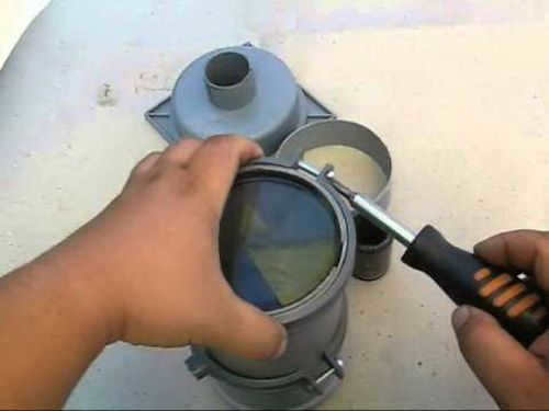
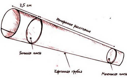
A Basic Refractor Telescope Design
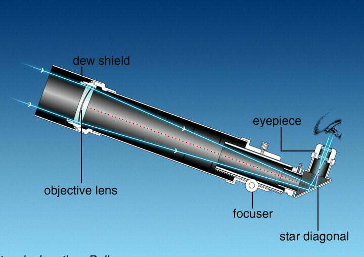
The most basic design for a refractor telescope consists of two convex lenses that magnify objects. The first lens, known as the objective lens, is larger and faces the sky. The second lens, called the eyepiece, is smaller and is used by the astronomer to observe. If you’re new to building telescopes, it’s recommended to follow this design when creating your own homemade telescope.
To achieve optimal results, it is recommended to use a high-powered magnifying lens as an eyepiece, preferably a magnifying glass attached to a handle. Such eyepieces were manufactured previously and can be easily obtained. Alternatively, an eyepiece from any commercially available optical device, such as binoculars or a geodetic device, can be used as well.
To determine the magnification that the telescope will provide, measure the focal length of the eyepiece in centimeters. Then, divide 100 cm (the focal length of a 1 diopter lens, which is the objective) by this measurement, and obtain the desired magnification.
Secure the lenses inside a sturdy tube (a cardboard tube coated with glue and painted with the darkest paint available will suffice). The eyepiece should be able to slide back and forth within a few centimeters, as this is necessary for focusing.
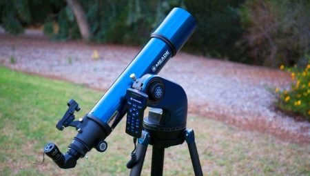
The wooden tripod with a Dobsonian mount is the ideal choice for mounting the telescope. You can easily find its design on any search engine. This type of mount is not only simple to construct but also highly dependable, which is why it is widely used in homemade telescopes.
Discover more about telescopes on our optical website:
- Which telescope is best for a child?Bringing back memories of childhood often evokes a sense of nostalgia, as everything seemed so big and far away, and there was a desire to learn and explore. I remember my parents talking about different constellations and Polaris.
- How to select a high-quality telescope for an amateur astronomerIf you have an interest in stars, then the question of how to choose a telescope for amateur astronomers becomes important. The key is not just the specifications and cost, but rather what you intend to use it for.