
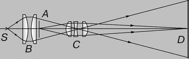
There are occasions when, due to different circumstances, we are unable to approach the subject we are examining and examine it in the necessary detail. Our eyes serve as a versatile tool: their sensitivity and resolution are restricted, and magnification is minimal. To expand our abilities, we employ telescopes. A telescope is an optical device created for observing remote objects.
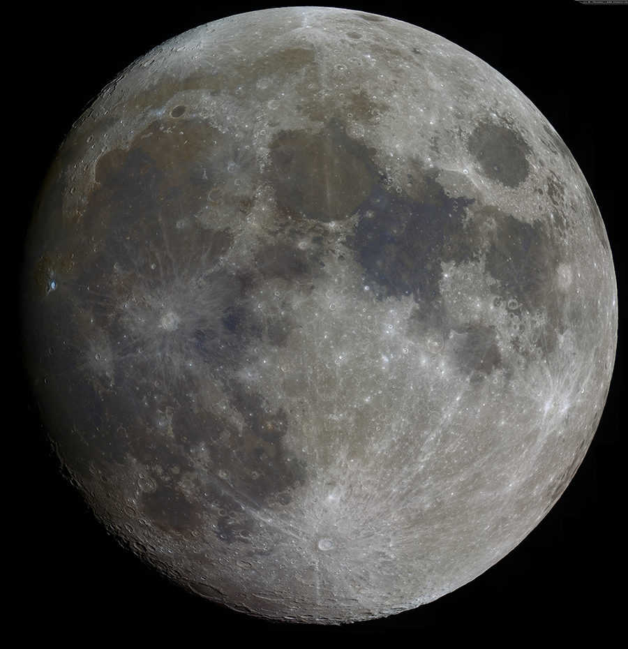
One of the primary benefits of utilizing a telescope is the ability to observe celestial objects at an increased angle of view. The human eye can only differentiate between two separate parts of an object if the angular distance is at least one minute of arc. Consequently, when looking at the Moon, the naked eye is only capable of perceiving larger portions with a cross-section exceeding 100 kilometers. Under favorable circumstances, such as when the Sun is obscured by haze, the naked eye can detect the largest sunspots on its surface. However, no other details on celestial bodies are discernible without the aid of a telescope. Telescopes amplify the angle of view by tens or even hundreds of times.
The second advantage of the telescope compared to the human eye is its ability to gather a significantly larger amount of light. Even in complete darkness, the human eye’s pupil has a diameter of only 8 mm. In contrast, the objective lens of a telescope has a much larger area, allowing it to collect much more light. The ratio of the areas of the objective lens and the pupil determines how much more light the telescope can gather. This ratio is equal to the square of the objective lens diameter divided by the square of the pupil diameter.
Telescopes are available in various types, including optical telescopes for general astrophysical observations, coronographs, telescopes for observing artificial satellites, radio telescopes, infrared telescopes, neutrino telescopes, and X-ray telescopes.
Download:
Preview:
To access the presentation previews, please create a Google account and log in here.
Slide captions:
Seeing the universe through the lens of an amateur astronomer. “The entire visible world is just a faint stroke within the vastness of nature” – B. Pascal. Author: Elizaveta Lopatina, 8th grade student. Supervisor: Irina Mikhailovna Studenetskaya.
Object of study: the Sun, the Moon Subject of study: telescope – refractor Objectives: To gain knowledge about the history of the telescope and its primary optical characteristics; To examine the devices, the path of light rays in optical telescopes, and identify the drawbacks that telescopes have when used for observation; To explore the amateur telescope “Galileo -200”, its specifications, and the techniques for observing distant objects; Hypotheses: 1. Increasing the eyepiece’s focal length will result in a decrease in the telescope’s magnification. 2. Increasing the magnification will lead to a decrease in the brightness of the observed celestial object and a narrower field of view. 3. Can chromatic aberration be observed with an amateur refractor telescope.
There are several methods used in the study of optical devices and physical phenomena:
- Method-Comparison: This method involves comparing one device with another to identify similarities and differences between them. For example, comparing a telescope-refractor and a telescope-reflector.
- Method-Generalization: This method involves identifying common properties and features among different types of optical devices and physical phenomena. For instance, establishing common features among different types of telescopes and physical phenomena such as refraction, diffraction, and aberration.
- Method-Observation: This method focuses on purposefully studying distant celestial objects and acquiring knowledge about them. It involves describing these objects using schemes and tables. For example, observing the Sun and the Moon.
Regarding the history of the telescope, it is worth mentioning two important figures:
- Galileo Galilei (1564-1642)
- Isaac Newton (1643-1727)
Refractor telescopes, also known as lens telescopes, are optical instruments used for viewing distant objects. The basic design of a refractor telescope consists of an objective lens, which is a double-convex lens, and a double-convex eyepiece. When light rays pass through the objective lens, they converge at a point called the focus. At this focus, a real image of the object being observed is formed. To magnify this image, an eyepiece is used.
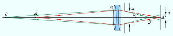
One common issue with refractor telescopes is chromatic aberration, which is the distortion of colors in the image. This occurs because different wavelengths of light are bent at different angles when passing through the lens. Another type of aberration is spherical aberration, which causes the image to be blurred or out of focus. Both chromatic and spherical aberration can affect the quality of the observed image.
The reflector telescope utilizes a mirror to focus the incident rays, positioning the focus between the lens and the object being observed. To view the image produced by the lens, an additional mirror is placed between the main mirror and its focus. This mirror redirects the rays reflected by the lens and guides the resulting image to either the side or through a hole in the center of the main mirror.
The mirror-lens telescope, also known as a catadioptric telescope, combines elements from both the reflector and lens systems to manipulate the path of the rays. Examples of mirror-lens telescopes include the Schmidt-Kassegren telescope and the Maksutov-Kassegren telescope.
Optical telescopes have several characteristics that define their performance. One such characteristic is the luminosity, which is determined by the ratio of the lens diameter to its focal length. This ratio, also known as the relative aperture, is expressed as a fraction, such as 1:5, 1:7, 1:10, or 1:15.
Another important characteristic is the magnification of the telescope. This is the ratio of the angle at which the image of an object is observed through the eyepiece to the angle at which the object would appear to the naked eye. The magnification determines how much closer the object appears when viewed through the telescope.
The resolving power of a telescope is another important characteristic. It refers to the telescope’s ability to distinguish fine details in extended objects, such as the disks of the Moon and planets, as well as its ability to separate nearby point objects, like stars. A telescope with high resolving power will be able to reveal more detail and sharpness in the observed objects.
The mounting of an astronomical telescope is also crucial for its design. It must allow the observer to easily point the telescope at a specific point in the sky and maintain its orientation as the Earth rotates, tracking the apparent motion of the object across the sky. A well-designed mounting ensures smooth and accurate tracking of celestial objects.
Radio telescopes are typically composed of a metal bowl in the shape of a paraboloid that functions as the lens. This lens collects the incoming signals, which are then received by an antenna placed at the focal point of the lens. The collected signals are then transmitted to a computer, which processes the data and generates images in standard colors. It is important to note that radio telescopes, similar to radio receivers, can only capture signals of a specific wavelength at any given time. The largest radio telescope, located near Arecibo in Puerto Rico at an elevation of 497 meters above sea level, is utilized for various research purposes in the fields of radio astronomy, atmospheric physics, and radar observations of celestial bodies within our solar system.
Infrared telescopes are devices that detect and capture heat waves, which are known as infrared waves. Just like radio telescopes, infrared telescopes are designed to receive signals at a specific wavelength. The design of infrared telescopes is similar to that of optical mirror telescopes. One famous example of an infrared telescope is the Hubble telescope, which is capable of recording electromagnetic radiation in the infrared range. In fact, in the infrared, the Hubble telescope is able to observe more galaxies than stars. Named after Edwin Hubble, a renowned American astronomer, the Hubble telescope was launched into space in 1990.
The X-ray telescope is specifically designed for observing distant objects in the X-ray spectrum. In order to function effectively, it must be positioned above the Earth’s atmosphere, which blocks X-rays. As a result, these telescopes are placed in Earth orbits. When a particle collides with the telescope, it generates a brief current pulse, which is recorded. The Chandra X-ray telescope, which was sent into orbit on July 23, 1999, was transported by the reusable Columbia spacecraft (mission STS-93). This telescope is the third of four large observatories launched by NASA between 1990 and 2003. It was named in honor of Subramanian Chandrasekhar, an Indian-born American physicist and astrophysicist.
An ultraviolet telescope is capable of capturing images in the ultraviolet range. Photographic film, specifically designed for this purpose, can also be used to capture ultraviolet rays. As a result, photographing ultraviolet images does not pose any significant challenges. Ultraviolet telescopes are built similarly to infrared or optical telescopes. Astronomers utilize ultraviolet telescopes to search for dwarf galaxies. In April 1972, astronaut John Young deployed an ultraviolet telescope on the Moon’s surface during a manned mission. Additionally, on April 28, 2003, the GALEX space telescope was launched into orbit to observe ultraviolet phenomena.
Astronomy enthusiasts use gamma-ray telescopes to explore the depths of outer space. These telescopes specialize in detecting and studying gamma waves, which are high-energy electromagnetic waves. By focusing on gamma rays, astronomers can gain valuable insights into various celestial objects that emit these short-wavelength rays. Gamma-ray telescopes are particularly useful for observing pulsars, neutron stars, and potential black holes found in active galactic nuclei.
One notable gamma-ray telescope is the HESS telescope, currently the most powerful of its kind. Located in Namibia, this telescope consists of four parabolic dishes, each with a diameter of 12 meters. These dishes are equipped with 382 circular mirrors, each measuring 60 cm in diameter. The entire telescope is situated on a 250-meter site, providing optimal conditions for celestial observations. Since its establishment in 2002, the HESS telescope has been actively contributing to our understanding of the cosmos.
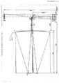
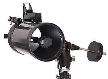
Research study. Specifications of the “Galileo-200” telescope Model: refractor telescope Lens diameter: 50mm Total length: 630mm Maximum stellar magnitude: 10.6 Mounting: altazimuthal Light sensitivity: 265 times greater than that of the human eye Image brightness (luminosity): 1:6 Lens focal length: 600 mm Magnification: 200X
Solar observation. As the distance between the screen and the eyepiece increases, the size of the Sun’s image grows while its brightness diminishes. As the magnification increases, the brightness of the observed celestial body decreases and the field of view narrows.
Solar observation. The longer the focal length of the eyepiece, the lower the telescope’s magnification:
Is it feasible to detect chromatic aberration in the Sun using a non-professional refractor telescope? It can be concluded that a chromatic aberration is visible as a colored halo surrounding the Sun’s disk.
The smallest angle of view that can be discerned by the naked eye is approximately 1 degree. This angle is influenced by the structure of the retina and the wave properties of light. There are various instruments, such as magnifying glasses, microscopes, and telescopes, that are designed to enhance the angle of vision. In visual observations, the eye is an integral part of the optical system, and the path of light rays in these devices depends on the eye’s ability to accommodate. When analyzing the functionality of optical instruments for visual observations, it is most convenient to assume that the observer’s eye is focused at infinity. This means that the rays from each point of the object, after passing through the device, enter the eye as a parallel beam. In such conditions, the concept of linear magnification becomes irrelevant. The ratio of the angle of view, when observing an object through an optical instrument, to the angle of view when observing it with the naked eye, is referred to as angular magnification.
Angular magnification is a significant feature of optical devices used for visual observation.
It is worth mentioning that certain textbooks make the assumption that the observer’s eye is adjusted to the distance of optimal vision for a regular eye, represented as d 0 . In such cases, the path of the rays within the instruments becomes slightly more complex, but the angular magnification of the device remains similar to when the eye is adjusted to infinity.
Magnifying Glass
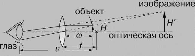
An uncomplicated device for optical observations is a magnifying glass. A magnifying lens is a converging lens with a short focal length (F < 10 cm). The magnifying glass is positioned near the eye, and the object is placed in its focal plane. The object is observed through the magnifier at an angular position of
where h represents the object’s size. When viewing the same object with the unaided eye, it should be positioned at a distance d 0 = 25 cm from the eye’s optimal visual point. The object will appear at an angular position of
Consequently, the angular magnification of the magnifying glass is equivalent to
A lens with a focal length of 10 cm provides a magnification of 2.5 times. The functionality of the magnifying glass is depicted in Fig. 6.1.1.
The function of the magnifying glass: a – the naked eye observes the object from the optimal vision distance d 0 = 25 cm; b – the object is observed through a magnifying glass with a focal length F.
Microscope
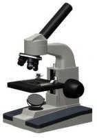 |
A microscope is utilized to achieve high magnifications while observing small objects. The enlarged image of an object in a microscope is achieved by means of an optical system comprised of two short-focus lenses – objective O 1 and eyepiece O 2 (Fig. 6.1.2).
The lens provides an actual inverted magnified representation of the object. The eye perceives this intermediate image through the eyepiece, which functions similarly to a magnifying glass.
The eyepiece is positioned so that the intermediate image aligns with its focal plane, causing the rays from each point of the object to spread out in a parallel beam after passing through the eyepiece.
The virtual image of the object seen through the eyepiece is always inverted. If this is inconvenient (such as when reading small text), the object itself can be inverted in front of the lens. Therefore, the angular magnification of the microscope is considered a positive value.
As depicted in Figure 6.1.2, the field of view of the object seen through the eyepiece can be approximated as a small angle.
Roughly speaking, we can assign d = F 1 and f = l, where l represents the separation between the objective and eyepiece of the microscope (“tube length”). When observing the same object with the unaided eye
Consequently, the equation for the angular magnification of a microscope adopts the following form
An exceptional microscope has the ability to provide a magnification of several hundred times. At higher magnifications, diffraction phenomena start to manifest.
In actual microscopes, the objective and eyepiece are intricate optical systems that have undergone the elimination of various aberrations.
Optical Instrument for Observing Distant Objects
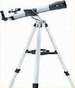 |
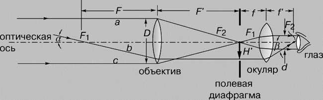
A telescope, also known as a telescope, is a device specifically designed for observing objects that are located at a distance. Its construction involves the use of two lenses – a larger collecting lens (known as the objective) with a long focal length, which is pointed towards the object, and a smaller lens (known as the eyepiece) with a shorter focal length, which is pointed towards the observer. There are generally two types of telescopes:
- Kepler’s telescope, which is primarily used for astronomical observations. It produces magnified, inverted images of distant objects and is not suitable for terrestrial observations.
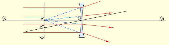
- Galileo’s telescope, originally designed for observing objects on Earth, produces enlarged and undistorted images. The eyepiece in Galileo’s telescope functions as a dispersing lens.
Fig. 6.1.3 illustrates the path of light rays in an astronomical telescope. It is assumed that the observer’s eye is focused on infinity, causing the rays from each point of a distant object to exit the eyepiece as a parallel beam. This type of ray path is referred to as “telescopic.” In order to achieve this telescopic ray path in the astronomical tube, the distance between the lens and eyepiece must be equal to the sum of their respective focal lengths (F = F1 + F2).
The telescope (telescope) is commonly defined by the angular magnification g . Unlike a microscope, objects observed in a telescope are always situated at a distance from the observer. If a distant object is observed with the naked eye at an angle j , and when viewed through a telescope at an angle y , the angular magnification is given by the ratio
Angular magnification g , similar to linear magnification, can have positive or negative values depending on whether the image is erect or inverted. The angular magnification of Kepler’s astronomical tube is negative, while that of Galileo’s terrestrial tube is positive.
The angular magnification of telescopes is expressed in terms of focal lengths:
The path of the rays in a telescope that can be extended.
Instead of lenses, large astronomical telescopes use spherical mirrors as the objective lens. These telescopes are known as reflectors. It is easier to create a good mirror, and unlike lenses, mirrors do not have chromatic aberration.
In our country, the world’s largest telescope with a mirror diameter of 6 meters has been constructed. It is important to note that large astronomical telescopes are designed not only to increase the angular distances between observed celestial objects but also to enhance the amount of light energy received from faintly luminous objects.
RU2154293C1 RU2154293C1 RU99101892A RU99101892A RU2154293C1 RU 2154293 C1 RU2154293 C1 RU 2154293C1 RU 99101892 A RU99101892 A RU 99101892A RU 99101892A RU 99101892 A RU99101892 A RU 99101892 A RU 99101892A RU 2154293 C1 RU2154293 C1 RU 2154293C1 Authority RU Russia Prior art keywords mirror lens meniscus telescope optical Prior art date 1999- 02-01 Application number RU99101892A Other languages English ( en ) Inventor E. R. Malamed I.E. Malamed I.E. R. Malamed I.E. Putilov M.N. Sokolsky L.M. Lapo Original Assignee Open Joint Stock Company "LOMO" Priority date (The priority date is an assumption and is not a legal conclusion. Google has not performed a legal analysis and makes no representation as to the accuracy of the date listed.) 1999-02-01 Filing date 1999-02-01 Publication date 2000-08-10 1999-02-01 Application filed by Open Joint Stock Company “LOMO” filed Critical Open Joint Stock Company “LOMO” 1999-02-01 Priority to RU99101892A priority Critical patent/RU2154293C1/ru 2000-08-10 Application granted granted Critical 2000-08-10 Publication of RU2154293C1 publication Critical patent/RU2154293C1/ru
Useful Links
- Espacenet
- Global Dossier
- Discuss
- 230000003287 optical Effects 0.000 claims abstract description 37
- 230000005499 meniscus Effects 0.000 claims abstract description 36
- 230000005693 optoelectronics Effects 0.000 claims description 6
- 239000000126 substance Substances 0.000 abstract 1
- 230000004075 alteration Effects 0.000 description 13
- 201000009310 astigmatism Diseases 0.000 description 11
- 206010010071 Coma Diseases 0.000 description 3
- 210000004279 Orbit Anatomy 0.000 description 3
- 21000000001747 Pupil Anatomy 0.000 description 2
- 23800000010276 Construction Methods 0.000 description 2
- 23900000011159 matrix material Substances 0.000 description 2
- 239000011248 coating agent Substances 0.000 description 1
- 23800000000576 coating method Methods 0.000 description 1
- 23900000000463 material Substances 0.000 description 1
Images
Summary
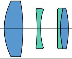
The present invention pertains to optical instruments, specifically space mirror-lens telescopes, and can be utilized to enhance their technical characteristics, such as achieving compact dimensions, wide angular field, and high linear resolution on the ground. The space mirror-lens telescope comprises a lens with mirror components – primary and secondary mirrors, a focal length converter that projects an intermediate image onto the plane of optoelectronic converter’s photosensitive elements. The focal length converter consists of a spherical or flat mirror and a lens component positioned in front of it, including a collective. An element deflecting the optical axis of the telescope is installed between the rear side of the main mirror and the focal length converter’s mirror. Additionally, the lens component can take the form of a positively curved meniscus facing the secondary mirror and a positive lens with higher optical power than the meniscus. The lens component also includes a first meniscus lens facing concavity towards the secondary mirror, and the spherical mirror has a reflecting layer applied to its convex surface. The lens component is equipped with a second meniscus lens placed along the path of the optical beam in front of the first meniscus lens, facing concavity towards it, and their optical powers satisfy the condition φ2< 0.02φ1 where φ1 represents the optical power of the first meniscus and φ2 represents the optical power of the second meniscus. The technical advantage achieved is the simplification of the design while maintaining a wide angular field and high linear resolution on the ground. 2 h.p., 1 tab., 4 il.
Description
The present invention pertains to optical instrumentation, specifically space mirror-lens telescopes, and can be utilized to enhance their technical characteristics. More specifically, it aims to achieve compact dimensions, wide angular field, and high linear resolution on the ground, which is particularly important in the advancement of small spacecraft.
Prior art includes mirror-lens lenses that consist of primary and secondary mirrors, lens field correctors, collective elements, and focal length converters that extend the latter [1]. However, these mirror-lens lenses have drawbacks such as large overall dimensions (system length) and the complexity of the focal length converter’s design, which is composed of multiple lenses.
The closest invention in terms of technical essence is a mirror-lens telescope with a main mirror, secondary mirror, lens field corrector, collective, focal length converter, and optoelectronic transducers (OEP) placed in the focal plane. The focal length converter is designed as a staggered matrix of lenses with optical axes parallel to the telescope’s optical axis. However, this design is complex and requires high image quality for the mirror-lens part of the telescope. The field aberrations cannot be corrected by the PFD projection lens because the optical axes of the PFR lenses intersect the intermediate image plane away from the telescope’s optical axis. Therefore, the primary and secondary mirrors and the lens-corrector must be independently corrected for aberrations, especially field aberrations, making the design complex and difficult to realize. Additionally, this telescope design needs an image synchronization unit connected to the optoelectronic converters.
The objective of the invention is to simplify the design while maintaining a large angular field and high linear resolution on the ground.
To address this issue, a space mirror-lens telescope is introduced, with the lens incorporating mirror components: primary and secondary mirrors, as well as a collective and a focal length converter that projects an intermediate image onto the plane of photosensitive elements of optoelectronic converters. In contrast to the prototype, the proposed telescope’s focal length converter consists of a spherical or flat mirror and a lens component placed in front of it, including a collective. An optical axis-deflecting element is positioned between the rear side of the main mirror and the focal length converter’s mirror.
Furthermore, as per claim 2, the assembly can be designed as a positive meniscus that is curved outwardly towards the secondary mirror, along with a positive lens that possesses a higher optical power than the meniscus. The lens component of the PFD includes a first meniscus lens that is concave towards the secondary mirror, while the spherical mirror is a reflective layer applied to its convex surface. According to Claim 3, the lens component is equipped with a second meniscus lens positioned along the path of the optical beam in front of the first meniscus lens, with its concave side facing towards it, and their optical powers must satisfy the following condition:
φ1 < 0.02φ2,
where φ1 refers to the optical power of the first meniscus lens, and φ2 represents the optical power of the second meniscus lens.
The main idea of the invention is that the intermediate image produced by a mirror or mirror-lens lens is projected onto the plane of photosensitive components of optoelectronic converters using a focal length converter. This converter consists of a spherical or flat mirror and a lens component placed in front of it. This arrangement allows for the correction of field aberrations of the mirror part. Additionally, the use of a deflecting element enables a more optimal layout of the circuitry, resulting in a compact, simple, reliable, and high-quality lens construction.
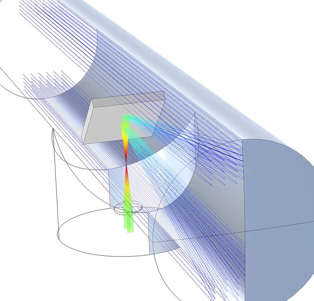
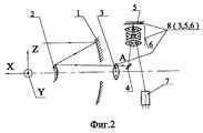
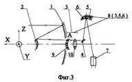
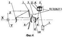
The essence of the invention is further illustrated in the accompanying drawings. Figures 1 and 2 depict different variants of the space mirror-lens telescope scheme for remote sensing of the Earth, as described in Claim 1. Figures 3 and 4, on the other hand, demonstrate alternative schemes of the telescope according to Claims 2 and 3, respectively.
Fig. 2 and 3 show a space mirror-lens telescope. In Fig. 1, there is a concave primary mirror 1, a convex secondary mirror 2, a collective 3, a flat mirror 4, a spherical mirror 5, and a two-lens component 6 in front of it. Additionally, there is an optoelectronic transducer 7, which is made up of linear or matrix photodetectors. The photosensitive elements of the transducer are located in the focal plane of the telescope. The collective 3, spherical mirror 5, and component 6 make up the transducer 8 with a focal length consisting of the main and secondary mirrors.
In Fig. 2, the focal length transducer 8 consists of the collective 3, the flat mirror 5, and the three-lens component 6 while maintaining the numbering of Fig. 1.
In the third illustration (FIG. 3), the PFD 8 includes a combination of components, namely the collective 3, a unique meniscus-shaped lens 6, and a concave mirror 5 that is formed by a reflective coating applied to the convex surface of the lens 6. The collective 3 is composed of a positive meniscus 9 that faces convexly towards the secondary mirror, and a positive lens 10 which possesses a higher optical power compared to the meniscus.
In the fourth illustration (FIG. 4), the PFD 8 of the space telescope is equipped with a collective 3 that consists of two positive menisks 9 and 10, a spherical mirror 5, and meniscus lenses 6 and 11 that face concave to each other. The optical powers of these components satisfy the condition
φ2 < 0.02φ1,
where φ1 represents the optical power of the first meniscus, and φ2 represents the optical power of the second meniscus.
The mirror layer on the convex surface of the meniscus lens 6 forms the concave mirror 5.
In all the schemes shown in Fig. 1-4, the PFD serves two purposes: it transforms the focal length of the mirror-lens telescope, making it equal to the product of the mirror lens’s focal length and the PFD magnification, and it acts as the field aberration corrector for the mirror lens.
The construction of the field aberration corrector (Fig. 3,4) can be summarized as follows: in the mirror lens 1,2, only two aberrations – spherical and coma – are corrected using aspherical surfaces with eccentricities e1 and e2, respectively. However, astigmatism and image curvature are not corrected and have large positive values.
The power mirror 5 with a spherical concave shape is used to achieve the desired magnification V of the PFD 8. This mirror introduces significant positive astigmatism and negative image curvature. As a result, it can compensate for the curvature of the image produced by the lens 1, 2, but the astigmatism is combined.
To correct for the astigmatism, a combination of two positive lenses is used. The intermediate image produced by the mirror lens 1, 2, which is located in the focal plane, is positioned between the first and last surfaces of the combination 3. This image is then depicted by the combination with a magnification close to unity. Additionally, the lenses of the combination are made of flint and crown materials. This design allows for the correction of chromatic aberration in the position and magnification of the combination itself.
The utilization of the primary lens from the collective three, taking the form of a positive meniscus nine, permits the introduction of negative astigmatism and minimal curvature. When combined with the second positive lens, it compensates for the astigmatism of mirror systems one, two, and five.
By incorporating the meniscus six in front of mirror five (Figures three, four), it becomes possible to introduce additional negative curvature to the image. As a result, the optical power of the concave mirror is chosen based on the condition of achieving the desired magnification V at the given dimensions, and the decompensation of image curvature is carried out by means of the meniscus six.
By adding a second meniscus 11 (Fig. 4), it becomes possible to correct for higher-order astigmatism without introducing any curvature to the images. The optical power of this second meniscus is negligible, not exceeding 0.02 times the optical power of the original meniscus 6.
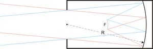
The functioning of the space mirror-lens telescope depicted in Figure 1 is as follows. While in orbit, the X axis of the space telescope is oriented towards Earth, and the mirror lens, composed of the primary mirror (1) and the secondary mirror (2) in its focal plane parallel to the Y axis (perpendicular to the drawing plane), constructs an image of the Earth’s surface in the form of a strip. This image is offset from the optical axis by l' (at point A in Figure 1). The collective (3) projects the entrance pupil of the telescope – the surface of the primary mirror (1) – onto the reflecting surface of the focal length transducer’s mirror (5). The flat mirror (4) deflects the rays. By introducing a displacement of the intermediate image by l' and utilizing the flat mirror (4), vignetting of rays in both the direct and reflected beams from mirror (5) can be eliminated. During orbital flight, the image of the Earth “moves” within the plane of the optoelectronic converters’ photosensitive elements (7), resulting in scanning of the object and the creation of an image of the strip. The width of this strip on the Earth’s surface is equal to 2y'H/f, where 2y' represents the length of the photosensitive zone of the optoelectronic converter, H is the orbit’s height, and f is the equivalent focal length of the telescope lens.
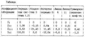
The appendix presents the optical layout, design parameters, residual aberrations, and frequency-contrast characteristics of the lens created based on the diagram shown in Figure 4. The telescope has a focal length of 6165 mm and a main mirror diameter of 600 mm. The distance between the main mirror (1) and the secondary mirror (2) is 750 mm. The maximum length of the telescope from mirror 2 (point 3 in the optical layout of the appendix) is 1102 mm. The central shielding coefficient is 0.31, and the working angular field in the object space is 1-3.
The focal length converter 8 consists of a collective 3 (represented by elements 5-8), a meniscus-shaped lens 6 with a mirror coating 5 on the convex surface (represented by elements 13-14 in the direct ray path), and a meniscus 9 (represented by elements 11, 12). It provides a linear magnification of V = 1.8145 and results in an equivalent focal length of f = V – f = 1.8145 – 3397.23 = 6165 mm.
Based on the theory of aberrations in optical systems, the Zeidei aberration coefficient characterizes each aberration of order III:
- SI – spherical aberration
- SII – coma
- SIII – astigmatism
- SIV – image curvature
The table displays the values of the aberration coefficients, providing insight into the role of each element in the aforementioned system.
According to the table, the collective element introduces negative astigmatism and compensates for the positive astigmatism of the entire PFD. Furthermore, mirror 5 and meniscus 6 compensate for the image curvature of the mirror system and partially of the collective element.
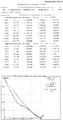
The optical scheme variant presented in the appendix meets the stringent image quality standards for telescopes in this category. It effectively corrects astigmatism at the periphery of the field of view, limiting it to a maximum of 0.06 mm. The average curvature at the edge of the field is 0.03 mm, while in the central zone it is 0.06 mm. The magnification chromatism is a mere 0.004%, ensuring accurate rendering of colors. Distortion is minimal at 0.5%, and meridional coma at the edge of the field measures 0.005 mm. Furthermore, the contrast at 42 mm is an impressive 0.51.
By incorporating a meniscus-shaped lens 6 with a reflecting surface 5 and a lens component in front consisting of a collective 3 and a meniscus 12, several advantages can be achieved. Firstly, it enables the creation of a focal length converter with a magnification V = 1.8145 and an equivalent focal length of the telescope of 6165 mm. Secondly, it allows for the positioning of the exit pupil on the mirror surface 5, resulting in a significant reduction in the overall dimensions and weight of lenses 6,9. Thirdly, it provides high-quality correction of field aberrations of the mirror system 1, 2.
Consequently, this particular design of a space telescope for remote sensing of the Earth, with a sufficiently large angular field and equivalent focal length, offers a simple, reliable, and compact solution. The length of the telescope is just 1.8 times the diameter (D) of its main mirror.
List of references
1. N.N. Michelson, “Optics of astronomical telescopes and methods of its calculation,” Physico-Mathematical Literature, 1995, pp. 328-331.
Claims ( 3 )
1. A space telescope with a mirror-lens system for remote sensing of the Earth, comprising a sequentially installed mirror lens that includes primary and secondary mirrors, a focal length converter, and optoelectronic converters located in the focal plane. The focal length converter is equipped with a spherical or flat mirror and a lens component positioned in front of it, which includes a collective lens. The mirror lens is designed to create an image of the Earth’s surface area.
2. The telescope, as described in paragraph 1, is distinguished by the configuration of the objective lens. The objective lens is shaped like a positive meniscus, with the convex side facing the secondary mirror. Additionally, there is a positive lens with a greater optical power than the meniscus. The lens component includes a first meniscus lens with a concave side facing the secondary mirror. Furthermore, the spherical mirror has a reflective layer applied to its convex surface.
(3) The Telescope described in Claim 2 includes a lens component that is equipped with a second meniscus lens. This lens is positioned along the path of the optical beam, in front of the first meniscus lens, and is concave facing towards it. The optical powers of these lenses satisfy the following condition:
φ2 < 0.02φ1,
where φ1 is the optical power of the first meniscus lens, and φ2 is the optical power of the second meniscus lens.
Priority Applications (1)
| RU99101892A RU2154293C1 ( ru ) | 1999-02-01 | 1999-02-01 | Telescope with a mirror-lens system for space observation |
Applications Asserting Precedence (1)
| RU99101892A RU2154293C1 ( ru ) | 1999-02-01 | 1999-02-01 | Space Mirror-Lens Telescope |
Articles (1)
ID=20215312
Related Articles (1)
| RU99101892A RU2154293C1 ( ru ) | 1999-02-01 | 1999-02-01 | Space Mirror-Lens Telescope |
Country Status (1)
Cited By (1)
| CN103018892A ( zh ) * | 2011-09-27 | 2013-04-03 | Boeing Company | T3 Module Architecture |
Cited By (2)
| CN103018892A ( zh ) * | 2011-09-27 | 2013-04-03 | Boeing Company | T3 Module Architecture |
| CN103018892B ( zh ) * | 2011-09-27 | 2017-04-12 | Boeing Company | T3 Module Architecture |
Documents with Similar Content
| CA2067021C ( en ) | 1999-01-26 | Powerless field-corrective lens |
| US7106529B2 ( en ) | 2006-09-12 | Flat wide-angle lens system |
| JP2566405B2 ( ja ) | 1996-12-25 | F-theta lens |
| US4512625A ( en ) | 1985-04-23 | Scanner optics with no cross scan field curvature |
| US4266848A ( en ) | 1981-05-12 | Optical system for night-vision glasses |
| KR101807414B1 ( ko ) | 2017-12-11 | Long-range oblique shooting camera optical system simultaneously shooting triple-band wavelength images |
| CN105511075A ( zh ) | 2016-04-20 | Optical system of large field-of-view swing scanning two-dimensional image shift compensation dual-channel imager |
| US6535332B1 ( en ) | 2003-03-18 | Infrared optical system for infrared cameras |
| US4850663A ( en ) | 1989-07-25 | Light scanning system |
| CN205581405U ( zh ) | 2016-09-14 | Visible light/infrared dual-band common caliber telephoto optical system |
| CN205539710U ( zh ) | 2016-08-31 | Optical system of large field-of-view swing scanning two-dimensional image shift compensation dual-channel imager |
| US6097545A ( en ) | 2000-08-01 | Concentric lens with aspheric correction |
| RU2443005C2 ( ru ) | 2012-02-20 | Catadioptric telescope |
| CN106019542B ( zh ) | 2018-08-03 | Wide-band multi-purpose continuous zoom optical system |
| RU2154293C1 ( ru ) | 2000-08-10 | Space mirror-lens telescope |
| US20220128796A1 ( en ) | 2022-04-28 | Small lens system for tof |
| US6819483B1 ( en ) | 2004-11-16 | Optical device and method for correcting field-dependent phase errors in distributed aperture telescope systems |
| US6356388B1 ( en ) | 2002-03-12 | Wide-angle catoptric focal system with mirrors |
| US5936780A ( en ) | 1999-08-10 | Projection zoom lens having a long back focal length |
| RU2521249C1 ( ru ) | 2014-06-27 | Mirror autocollimation spectrometer |
| JPH10142497A ( ja ) | 1998-05-29 | Infrared optical system |
| RU2650055C1 ( ru ) | 2018-04-06 | Catadioptric telescope |
| RU2248024C2 ( ru ) | 2005-03-10 | Catadioptric telescope |
| US20020149856A1 ( en ) | 2002-10-17 | External pupil lens system |
| US20220128795A1 ( en ) | 2022-04-28 | Small lens system for tof |
We are all brilliant individuals. However, if you assess a fish based on its capacity to climb a tree, it will spend its entire existence believing it is foolish.
Albert Einstein

Exam Queries
For students from all technical groups at the Nvorossiysk College of Construction and Economics (NCCE).
Welcome to my webpage!
LET’S GET ACQUAINTED
My name is Elena Viktorovna.
I am a teacher and tutor with 26 years of experience.
I assist students in understanding the school curriculum. I provide preparation for the USE.
We continue learning throughout our lives.
And if you have come to my website, then you certainly have one desire! The desire to learn!
- comprehend physics
- enhance physics grades
- overcome fear of lessons
- deepen the study of physics
- Get ready for the USE examination in physics
If you follow a systematic, step-by-step practice approach, physics becomes easy! If you need assistance, feel free to reach out to us!
We offer both online and in-person classes*. (*Note: in-person classes are available only in Novorossiysk).
Lesson 49. Lenses. Optical instruments.
Optical instruments are devices that transform the radiation from different regions of the spectrum (such as ultraviolet, visible, and infrared) through transmission, reflection, refraction, or polarization.
By convention, optical instruments are commonly associated with devices that operate in the visible light range.
During the initial evaluation of an instrument’s quality, only its basic characteristics are considered:
- Luminosity refers to the capacity to concentrate radiation.
- Resolving power denotes the ability to differentiate neighboring details within an image.
- Magnification represents the ratio of an object’s size to its image.
- For numerous instruments, the key characteristic is the field of view, which is the angle at which the outermost points of an object can be seen from the center of the instrument.
Resolving power (ability) characterizes the capability of optical instruments to generate distinct images of two closely positioned points on an object.
The linear or angular limit of resolution refers to the smallest linear or angular distance between two points at which their images merge.
The wave nature of light is responsible for the ability of an instrument to differentiate between two closely spaced points or lines. The resolving power of a lens system, for instance, is determined by the designer’s skill in managing lens aberrations and precisely aligning the lenses on the same optical axis. The theoretical limit of resolution for two adjacent imaged points is defined as the distance between their centers being equal to the radius of the first dark ring in their diffraction pattern.
Magnification. If an object with a length of H is perpendicular to the optical axis of the system and its image has a length of h, the magnification m can be calculated using the following formula:
Magnification is dependent on the focal lengths and the relative arrangement of the lenses. There are corresponding formulas available to express this dependence.
An important feature of visual observation instruments is the apparent magnification M. It is determined by the ratio of the size of the images of the object formed on the retina when observing the object directly and through the device. Typically, the apparent magnification M is expressed as the ratio M = tgb / tga where a is the angle at which the observer sees the object with the naked eye, and b is the angle at which the observer’s eye sees the object through the instrument.
The lens is a fundamental component of any optical system. Lenses are present in nearly all optical instruments.
Lens – an optically transparent object bounded by two spherical surfaces.
A lens is classified as a thin lens if its thickness is significantly smaller than the radii of curvature of its spherical surfaces.
There are two types of lenses: converging lenses and diverging lenses. A converging lens is thicker in the middle and thinner at the edges, while a diverging lens is thinner in the middle and thicker at the edges.
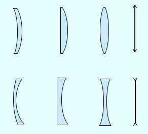
- convex:
- birefringent (1)
- flat-convex (2)
- concave-convex (3)
- concave:
- biconcave (4)
- flat-concave (5)
- convex-concave (6)
Basic notations in a lens:
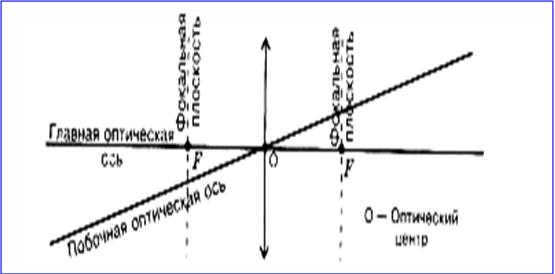
The principal optical axis of the lens is the straight line that passes through the centers of curvature O1 and O2 of the spherical surfaces.
For thin lenses, it can be approximated that the principal optical axis intersects the lens at a single point, known as the optical center of the lens O. Light rays passing through the optical center of the lens do not deviate from their original direction.
The optical center of the lens is the point where light rays pass through without being refracted.
The principal optical axis is a straight line that is perpendicular to the lens and passes through the optical center of the lens.
All lines intersecting at the center of the lens are known as collateral optical axes.
If a bundle of rays that are parallel to the main optical axis is aimed at the lens, these rays (or their extensions) will converge at a single point F after passing through the lens. This point is referred to as the main focus of the lens. A thin lens possesses two principal focuses that are symmetrically positioned along the main optical axis in relation to the lens. The focal points are real for converging lenses and imaginary for diverging lenses.
When a bundle of rays that are parallel to one of the side optical axes pass through the lens, they also converge at the point F', which is found at the intersection of the side axis and the focal plane F. This focal plane is perpendicular to the main optical axis and passes through the main focus.
The focal plane is defined as a line that is perpendicular to the lens’s principal optical axis and passes through the lens focus.
The focal length is the distance between the lens’s optical center O and its principal focus F, and it is represented by the letter F.
The process of a parallel beam of rays being refracted in a converging lens.
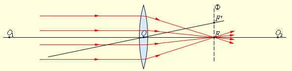
The bending of a parallel beam of light in a lens that scatters the rays.
The centers of the spherical surfaces are denoted by points O1 and O2. The main optical axis is denoted by O1O2 and the optical center is denoted by O. The main focus is denoted by F, while the side focus is denoted by F’. The side optical axis is denoted by OF’. The focal plane is denoted by F.
When depicted in drawings, thin lenses are shown as segments with arrows:
collecting: 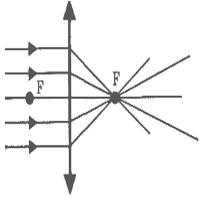 scattering:
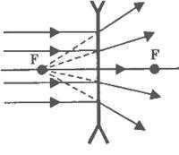
The primary characteristic of lenses is their ability to create images of objects. These images can be direct or inverted, real or imaginary, and magnified or reduced.
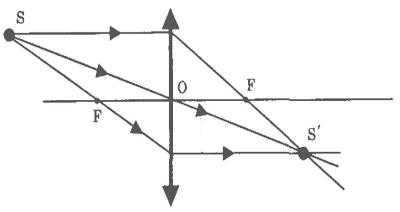
Geometric constructions can be used to determine the position and nature of an image. To do this, we employ the properties of certain standard rays whose paths are well-known. These rays include those that pass through the optical center or one of the focal points of the lens, as well as rays that are parallel to the main or one of the side optical axes. To construct an image in the lens, any two out of the three mentioned rays are utilized:
The thin lens formula can be used to calculate the position and nature (real or virtual) of an image. It is expressed in terms of the distance from the object to the lens (denoted as d) and the distance from the lens to the image (denoted as f). The formula can be written as:
The reciprocal of the focal length, D, is referred to as the optical power of the lens.
The unit of measurement for optical power is the dioptre (dptr). A dioptre is the optical power of a lens with a focal length of 1 meter: 1 dptr = m -1
Focal lengths of lenses are typically assigned specific signs: a converging lens has a positive focal length (F > 0), while a diverging lens has a negative focal length (F < 0).
The values of d and f are subject to a certain rule regarding their signs:
d>0 and f>0 – for real objects (i.e. actual light sources, not extensions of converging rays) and images;
d
Thin lenses have several drawbacks that prevent the creation of high-quality images. The distortions that occur during image formation are known as aberrations. The primary ones include spherical aberration and chromatic aberration.
Spherical aberration occurs when wide beams of light cause rays far from the optical axis to cross it out of focus. The thin lens formula is only valid for rays near the optical axis. The image of a distant point source created by a wide beam of refracted rays is blurry.
The phenomenon of chromatic aberration occurs due to the fact that the refractive index of the lens material varies depending on the wavelength of light λ. This property, known as dispersion, causes the focal length of the lens to differ for different wavelengths of light, resulting in image blurring when non-monochromatic light is used.
In modern optical devices, thin lenses are no longer used. Instead, complex multi-lens systems are employed to approximate various aberrations.
The formation of the actual object image is achieved through the use of a collecting lens in numerous optical devices such as cameras, projectors, and more.
To create a high-quality optical device, optimizing its fundamental characteristics such as aperture, resolution, and magnification is essential. Merely achieving a large apparent magnification while keeping the aperture small will not result in a good telescope. The resolution would suffer since it directly depends on the aperture size. Optical device designs vary greatly, with their features determined by the specific purpose of each device. However, when transforming a designed optical system into a finished optical-mechanical device, it is crucial to arrange all optical elements in strict accordance with the adopted scheme. They should be securely fixed, and the position of moving parts must be accurately adjusted. Additionally, apertures should be placed strategically to eliminate unwanted background scattered radiation. Maintaining specified temperature and humidity levels inside the device is often necessary, along with minimizing vibrations, normalizing weight distribution, and ensuring heat dissipation from lamps and other auxiliary electrical equipment. Attention is also given to the appearance of the instrument and ease of handling.
Microscope, magnifier, magnifying glass.
If you look through a positive (collecting) lens at an object positioned behind the lens within its focal length, you will observe a magnified virtual image of the object. This type of lens is the most basic form of microscope and is commonly referred to as a magnifying glass or magnifier.
The size of the magnified image can be determined from the optical configuration.
A telescope is a device that enlarges the apparent size of faraway objects. It is composed of two positive lenses, making it the most basic form of a telescope.
Binoculars, also known as a binocular telescope, are a small device that allows you to observe with both eyes simultaneously. They typically have a magnification of 6 to 10x. Binoculars utilize a pair of turning systems, usually Porro prisms, which consist of two rectangular prisms positioned at a 45° angle to each other, with opposite rectangular faces.
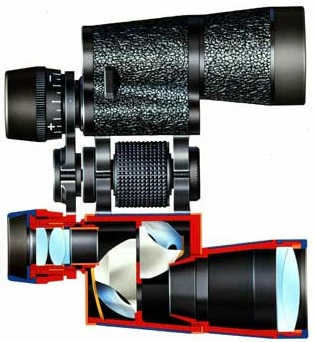
In order to achieve a wide field of view with a high magnification, binoculars require an eyepiece of superior quality, surpassing that of a telescope with a narrower field of view. This superior eyepiece allows for image focusing and vision correction, as indicated by the diopter scale. Additionally, the position of the eyepiece in binoculars can be adjusted to accommodate the distance between the observer’s eyes. Binoculars are typically labeled based on their magnification (in multiples) and objective lens diameter (in millimeters), such as 8*40 or 7*50. These specifications ensure a large angle of view (6-9°) and minimize lens aberrations.
Any telescope that is intended for observing things on land can also be used as a sighting device, as long as specific marks or symbols are added to its image space to serve a particular purpose. In many military optical installations, the telescope lens is positioned openly towards the target, while the eyepiece remains hidden. This setup requires a bend in the optical axis of the sight, which is compensated for by using prisms. These prisms also convert the inverted image into a straight image. Systems that have an offset optical axis are known as periscopic systems. Typically, a telescopic sight is designed in a way that the exit pupil is located at a sufficient distance from the last surface of the eyepiece, ensuring that the gunner’s eye is protected from coming into contact with the edge of the telescope when the weapon recoils.
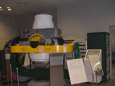
There are two types of optical rangefinders used to measure distances to objects: monocular and stereoscopic. While they have different constructional details, the main part of the optical scheme and the principle of operation remain the same. The principle involves determining an unknown side of a triangle from a known side (base) and two known angles of the triangle. In the case of optical rangefinders, two parallel telescopes, separated by a distance b (base), capture images of the same distant object but from different directions. By aligning the image fields of both telescopes using an optical device, the corresponding images of the object appear spatially separated. Some rangefinders achieve this through full field superposition, while others use half field superposition. In the latter, the upper half of one telescope’s image space is combined with the lower half of another telescope’s image space. To combine these spatially separated images and determine the measured value, a suitable shifting element is used, often in the form of a prism or a combination of prisms.
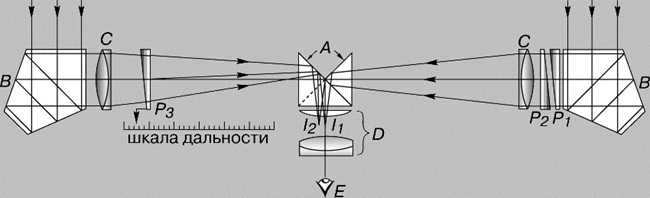
MONOCULAR RANGEFINDER. A – rectangular prism; B – pentaprism; C – objective lens; D – eyepiece; E – eye; P1 and P2 – fixed prisms; P3 – movable prism; I1 and I2 – images of half of the visual field
The prism P3 in the monocular rangefinder scheme shown in the illustration performs the task of measuring distances to objects. It is connected to a scale that is calibrated in measured distances. To ensure accurate deflection of the incident light beam by 90 degrees, pentaprisms B are used as reflectors of light at right angles. Their installation in the horizontal plane of the instrument does not affect their ability to deflect the light beam. In a stereoscopic rangefinder, the observer uses two telescopes to see images with both eyes simultaneously. The base of the rangefinder allows the observer to perceive the object’s position in three-dimensional space. Each telescope is equipped with a grid containing range values. By observing the distance scale extending into the imaged space, the observer can determine the distance of the object.
Lighting and projection devices. Projectors.
In the optical scheme of a spotlight, the light source, like the electric arc discharge crater, is positioned at the focal point of a parabolic reflector. Rays emitted from all points of the arc are almost parallelly reflected by the parabolic mirror. The ray beam slightly spreads because the source is not a luminous point but a volume with a finite size.
The arrangement of lenses in this device, intended for observing transparent images and colored frames, consists of two lens systems: a condenser and a projection lens. The condenser evenly lights up the transparent original, guiding the light rays into the projection lens, which creates a replica of the original on the screen. The projection lens allows for focusing and interchangeable lenses, enabling adjustments to the screen distance and image size. The optical configuration for a film projector follows a similar pattern.
DIASCOPE SCHEME. A – diapositive; B – lens condenser; C – projection lens; D – screen; S – light source
The dispersive prism or diffraction grating can serve as the primary component of a spectral device. In this type of device, the light is initially collimated, meaning it is transformed into a beam of parallel rays. Next, it is separated into a spectrum, and finally, the image of the input slit of the instrument is focused onto the output slit at each wavelength of the spectrum.
Within this highly versatile laboratory device, the collimating and focusing mechanisms have the ability to rotate around the central axis of the stage, where the component responsible for separating light into a spectrum is positioned. The instrument is equipped with scales that enable the precise measurement of rotation angles, such as those of the dispersion prism, as well as the angles of deviation exhibited by various color components within the spectrum. By analyzing these readings, it becomes possible to determine important properties of transparent solids, such as their refractive indices.
This instrument is called a spectrograph, which captures or records a spectrum, or a portion of it, on photographic material. A spectrum can be obtained using a prism made of different materials such as quartz (210-800 nm), glass (360-2500 nm), or rock salt (2500-16000 nm). When prisms weakly absorb light in certain ranges of the spectrum, the spectral lines appear bright in the images produced by the spectrograph. Spectrographs with diffraction gratings have two functions: they disperse the radiation into a spectrum and focus the different colors onto the photographic material. These devices are also used in the ultraviolet region.
A camera is a light-tight, enclosed device. It captures the image of objects using a system of lenses known as a lens. The lens is opened for a specific duration of time using a special shutter, allowing the image to be recorded on the photographic film.
The unique aspect of how the camera operates is that it requires objects at different distances to be captured with sufficient sharpness on a flat film.
Only objects at a specific distance are captured with sharpness on the film plane. This sharpness is achieved by adjusting the position of the lens in relation to the film. Objects that are not within this plane appear as blurry circles. The size of these circles, denoted as d, can be reduced by adjusting the aperture of the lens, or the relative aperture a/F. This adjustment increases the depth of field, resulting in a greater range of objects appearing in focus.
The optical systems of a modern camera are made up of multiple lenses, such as the Tessar optical scheme. The number of lenses in the simplest camera lenses ranges from one to three, while in high-end cameras, the number can increase to ten or even eighteen.
There can be anywhere from two to five optical systems within a lens. Virtually all optical configurations are structured and operate in a similar manner – they concentrate the light rays that pass through the lens onto the photosensitive matrix.
The quality of the photograph is solely dependent on the lens. It determines whether the image will be sharp, if it will accurately represent shapes and lines, and if it will accurately depict colors. Therefore, the lens is considered one of the most crucial components of a modern camera.
Lenses are crafted from specialized types of optical glass or optical plastic. The creation of lenses is a highly costly process in camera production. When comparing glass and plastic lenses, it is important to note that plastic lenses are more affordable and lighter in weight. In the present day, plastic lenses are predominantly used in inexpensive amateur compact cameras. However, these lenses are susceptible to scratches and lack durability, as they tend to become cloudy after approximately two to three years of use, resulting in subpar photo quality. On the other hand, the optics of pricier cameras are composed of optical glass.
In the contemporary era, the majority of compact camera lenses are constructed from plastic.
Lenses are either fused together or secured with meticulously calculated metal frames. Fused lenses are significantly more prevalent than those with metal frames.
A projection device is specifically designed for creating large-scale images. The lens of the projector, labeled as O, focuses the image of a flat object (referred to as diapositive D) onto a distant screen labeled as E. A lens system known as K, also called a condenser, is used to focus the light from a source S onto the diapositive. An enlarged and inverted image is then projected onto the screen E. The magnification of the projection device can be adjusted by altering the distance between the screen E and the diapositive D while also changing the distance between the diapositive and the lens O.
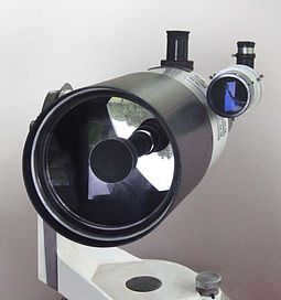
Mirror-lens optical systems or catadioptric systems are a type of optical systems that incorporate both mirrors (catoptrics) and lenses as essential components. Mirror-lens systems have been utilized in various applications such as searchlights, headlights, early lighthouses, microscopes, telescopes, telephoto lenses, and superluminous lenses.
Catadioptric systems have primarily been developed in the field of telescopes due to their utilization of a spherical mirror surface, which is more technologically advanced than other curved surfaces. This advancement allows for the construction of larger diameter telescopes at a relatively lower cost. Reflector telescopes can incorporate correcting lenses of smaller diameters to expand the useful field of view, but they are not classified as mirror-lens telescopes. Mirror-lens telescopes, on the other hand, feature lens elements that are similar in size to the main mirror and are specifically designed to correct the image produced by the main mirror.
Overview of the fundamental optical systems employed in catadioptric telescopes
As per the principles of optics, the roughness of the mirror surface must be of an acceptable quality, no worse than λ/8, where λ represents the wavelength (in this case, visible light at 550 nm). Additionally, the surface shape should deviate within the range of 0.02 µm to 1 µm [1]. Therefore, the primary challenge in mirror fabrication lies in the precise observation of the surface curvature. Creating a spherical mirror is technologically simpler compared to manufacturing aspherical shapes such as elliptical, parabolic, hyperbolic, and flattened spheroid mirrors, which are commonly utilized in telescope reflectors. However, spherical mirrors themselves suffer from significant spherical aberrations, rendering them unsuitable for use. The telescope systems described below represent efforts to correct these aberrations by incorporating a glass lens (or lens system) with a specialized curvature (corrector).
The initial catadioptric telescope systems [ edit corrected code ].
The initial varieties of catadioptric telescopes incorporated systems comprising of a single-lens objective and a Mangen mirror. The first telescope with this design was patented by W. F. Hamilton in 1814. Near the conclusion of the 19th century, German optician Ludwig Schupmann positioned a catadioptric mirror behind the focal point of the single-lens objective and added a third component to the system – a lens corrector. However, these telescopes did not gain widespread popularity and were overshadowed by achromatic refractors and reflectors. It is worth noting that towards the end of the 20th century, some opticians once again displayed interest in these configurations: for instance, in 1999, British amateur astronomer and telescope builder John Wall patented the optical design of the Zerochromat telescope.” [2]
Schmidt system [ edit edit code ]
Schmidt Camera [ edit correct code ].
The Schmidt chamber operates based on the principle of the lensless Schmidt. In 1930, Bernhard Schmidt, an Estonian-Swedish optician working at the Hamburg Observatory, made a significant modification to the chamber. He replaced the limiting aperture with an aspherical planoidal spherical aberration corrector, which effectively eliminated both coma and astigmatism. To further address spherical aberration, Schmidt inserted a specially shaped lens into the aperture. This lens has a 4th order surface.
“The outcome was a photographic camera that had only one flaw – field curvature, but it also possessed remarkable qualities: the higher the camera’s brightness, the better the resulting images and the wider the field of vision” [3].
(This refers to cameras with the same aperture.) Schmidt cameras may exhibit some slight chromatic aberration, although it is usually not of practical significance. Some versions have a dual-achromatic correction plate. The Schmidt camera is widely utilized in astrometry for creating sky surveys. Its primary advantage lies in its exceptionally large field of view, reaching up to… 6 degrees. As the focal surface is spherical, astrometrists typically do not correct for field curvature and instead employ curved photographic plates.
Schmidt-Väisälä camera [ edit correct code ].
Irjo Väisälä, an optician from the Principality of Finland in the Russian Empire, independently came up with a similar concept to Schmidt’s, but did not publish it. Instead, he made a note in his 1924 lecture notes titled “problematic spherical focal surface”. When Väisälä saw Schmidt’s publication, he devised a solution to correct the curvature of the image surface by adding a double-convex lens near the focal point. This design became known as the Schmidt-Väisälä Camera, or sometimes simply the Väisälä Camera. The Schmidt-Väisälä Camera was further developed in the RASA scheme. However, it deviated from the Schmidt-Cassegrain telescope by not placing the aperture corrector at the center of curvature of the main mirror, and it also had a reduced length of over 50%.
RASA camera [ edit edit code ]
Row Ackermann Schmidt Astrograph – An astrograph based on a design similar to the Schmidt camera, but using an aspherical planoidal Schmidt corrector modified by Rove and Ackermann. This astrograph is essentially an evolution of the Schmidt-Väisäl camera design, featuring a complex pre-focal four-lens corrector (instead of a single double-convex lens) and a shorter overall length, comparable to the Schmidt-Kassegren telescope. The full-aperture corrector is positioned slightly closer to the focal length.
Celestron has introduced the RASA camera, a 280 mm (11″) F/2.2 model equipped with a traditional full-aperture Schmidt corrector and a four-lens close-focal image curvature corrector.
Mounting traditional SLR cameras on the RASA camera can be done in a rather unconventional manner: placing it in front of the telescope, right next to the corrector glass at its center. This setup results in a portion of the aperture being covered by the camera body.
With its exceptional image quality, the RASA camera offers an unusually large aperture for amateur telescope astrographs at an affordable price. Additionally, it provides a remarkably wide field of view measuring 70 mm.
Schmidt-Cassegrain Telescope [ edit correct code ].
can be paraphrased as
Modifying the Code for the Schmidt-Cassegrain Telescope.
The preservation of the original correction plate position, as in the Schmidt camera, maintains high quality on a wide field. However, the diffraction pattern is compromised due to the need to introduce an attachment for the secondary mirror, which is implemented on regular spider stretchers. Additionally, the telescope remains heavy and has a long length.
Maksutov’s Meniscus Schmidt [ edit edit code ]
Rephrase the text, making it unique and keeping the HTML markup:
Maksutov’s Meniscus Schmidt [ edit edit code ]
The renowned Soviet optician D.D. Maksutov, who is well-known for his meniscus system, also introduced a highly significant optical design that is unfortunately not widely recognized – a meniscus variation of the Schmidt camera. (This design was also independently proposed by the Dutch optician Albert Bowers.) The design consists solely of spherical surfaces and offers a wider, distortion-free field compared to the original Schmidt design with an aspherical plate corrector! Despite its relative simplicity, it is more accessible for industrial development and can be independently manufactured by amateurs, in contrast to the Schmidt camera with an aspherical corrector. However, it also provides better quality and a larger aperture than the “lens-less Schmidt” design. Among its drawbacks, it is important to note the chromatism of position (due to a single non-achromatized meniscus), a similar length to that of Schmidt’s camera, and the limited availability of completely eliminating spherical aberration in certain cases, which closely resembles the “superschmidt” designs – more complex and advanced.
Baker-Nahn camera [ edit edit code ]
The Baker-Nahn camera is a remarkable piece of technology that has revolutionized the field of photography. It has been widely praised for its innovative design and advanced features. The camera is a favorite among professional photographers for its exceptional image quality and versatility.
One of the standout features of the Baker-Nahn camera is its ability to capture images with incredible clarity and detail. The high-resolution sensor and advanced optics ensure that every shot is sharp and vibrant. Whether you are capturing landscapes, portraits, or action shots, the Baker-Nahn camera will deliver stunning results.
In addition to its image quality, the Baker-Nahn camera also offers a range of creative options for photographers. It has a variety of shooting modes, including manual, aperture priority, and shutter priority, allowing photographers to have full control over their images. The camera also has a selection of creative filters and effects that can be applied to photos in-camera, saving time and effort in post-processing.
The Baker-Nahn camera is also known for its exceptional build quality. It is made from high-quality materials that ensure durability and longevity. The camera is also weather-sealed, making it suitable for shooting in various conditions. Whether you are shooting in the rain or in dusty environments, the Baker-Nahn camera will continue to perform at its best.
Overall, the Baker-Nahn camera is a top choice for professional photographers who demand the best. Its outstanding image quality, creative options, and robust build make it a reliable tool for capturing stunning photos. Invest in the Baker-Nahn camera, and you won’t be disappointed.
James Baker and Joseph Nan implemented a modification to Schmidt’s camera by placing a three-lens system closer to the focus instead of the aspherical corrector. This modification resulted in the creation of the Baker-Nahn camera. The Baker-Nahn camera was used for satellite observation and featured a 50 cm F/0.75 lens. It utilized large format 55 mm film known as “Cinemascope 55”. The camera was utilized by the Smithsonian Astronomical Observatory from the late 1950s to the mid-1970s.
Superschmidts [ edit correct code ].
These optical systems are the most advanced mirror-lens systems available, offering an exceptionally wide field of view (up to 65° degrees) and a luminosity that approaches the theoretical limit. The superchmidt family of optical systems includes the following:
- Linfoot-Hawkins
- Bowers
- Volosov-Babintsev (“Antares”)
- Maksutov-Sosnina (Astrodar)
- Baker
The designs are derived from the design of “Maksutov’s meniscus Schmidt” with the incorporation of an additional corrective element, which can exist in aspherical variations: Schmidt corrector or double-lens aspherical corrector (such as Linfoot-Haukins systems and Maksutov-Sosnina’s “Astrodar” lens with a 30° field of view diameter, geometric aperture of 1/1.4, and effective aperture of 1/1.8), as well as in the form of a conical lens: the Bowers and “Volosov-Babintsev” systems (using the Antares lens). Professor James Gilbert Baker’s Superschmidt has a geometric aperture of 1/0.67 at a 55° field of view angle and an aperture of 300 mm (with a mirror diameter of 585 mm and a meniscus diameter of 457 mm).
The Maksutov system [ edit correct code ].
In 1941, D. D. Maksutov made a groundbreaking discovery when he found a way to compensate for the spherical aberration of the main mirror in telescope systems. He achieved this by incorporating a meniscus lens with a large curvature. While the main mirror is typically spherical, some systems opt for elliptical main mirrors or undergo specific modifications to improve performance. By carefully determining the optimal distance between the meniscus lens and the mirror, Maksutov successfully eliminated coma and astigmatism. Additionally, field curvature, similar to the Schmidt camera, can be addressed by introducing a flat-convex lens near the focal plane, commonly known as the Piazzi-Smith lens.
By applying a process of aluminizing to the central portion of the meniscus, Maksutov successfully created meniscus versions of the Cassegrain and Gregory telescopes. There have been suggestions for meniscus adaptations of almost all telescopes that are of interest to astronomers. Particularly popular in modern amateur astronomy are the Maksutov-Cassegrain telescopes, and to a lesser extent, the Maksutov-Newton telescopes. Other Maksutov designs, like the Maksutov-Gregory, are not as widely used.
It is important to mention that there are three primary variations of Maksutov-Kassegren meniscus telescopes, each differing in the type of secondary mirror.
In one scenario, the secondary mirror, as previously stated, takes the form of an aluminized circle on the inner surface of the meniscus. This design choice simplifies the construction process and reduces costs. However, due to the matching radii of curvature on the outer and inner surfaces of the meniscus, the focal ratio of the system must be increased in order to eliminate spherical aberration and achieve acceptable performance. As a result, the majority of commercially available small telescopes in the amateur class have long focal lengths and focal ratios ranging from 1/12 to 1/15.
In English-language sources, telescopes of this design are commonly known as Gregory-Maksutov or Spot-Maksutov. The name comes from the fact that the U.S. patent for this scheme, including the type of secondary mirror, was granted to American optician and engineer John F. Gregory (1927-2009). The Questar, which was produced in 1954, is considered to be the first commercial amateur telescope of this type.
To create larger aperture systems and high-end telescopes, a separate secondary mirror is used. This mirror is either attached to the meniscus or, as was done in the Soviet “MTO” and “ZM” lenses, forged directly onto the meniscus, forming one part with it. Having a separate mirror allows for the necessary geometric shape without altering the design of the meniscus. In English-language sources, this version of the Maksutov telescope is referred to as Maksutov-Sigler.
There is an alternative design of the Maksutov telescope with a converging beam that incorporates a meniscus corrector. In this design, the meniscus is not the same size as the full aperture, but rather matches the size of the secondary mirror and is positioned close to it. The light rays pass through the meniscus twice – once before reflecting off the secondary mirror and again after reflection. This particular design has been further refined in the Argunov and Klevtsov schemes.
When comparing the standard Schmidt-Cassegrain systems (not to be confused with elongated tube Schmidt cameras, which have a tube length about 3 times longer and place the corrector at a double focal distance from the mirror), the Maksutov-Cassegrain system exhibits residual spherical aberration (while well-made Schmidt systems have no spherical aberration at all). As a result, Maksutov-Cassegrain systems are constructed with a relative aperture that is approximately 30%-50% larger than Schmidt-Cassegrain systems in order to achieve excellent image quality. However, the Maksutov-Cassegrain system surpasses the Schmidt-Cassegrain system in all other aspects, including reduced image surface curvature, less coma, and a larger undistorted field of view. Furthermore, the Maksutov-Cassegrain system eliminates the minor chromaticity present in the Schmidt-Cassegrain system.
Volosov-Galpern-Pechatnikova (Slefogt-Richter) system [ edit correct code ].
A system employing a full-aperture lens corrector, utilizing two lenses as the corrector. This system has been implemented in Soviet and currently Russian Rubinar lenses.
Hamilton system [ edit edit code ]
One of the initial amateur photographic lenses utilizing the Hamilton system: the Minolta RF Rokkor-X 250 f/5.6, 1979.
Since the late 1970s, one of the most widely used optical configurations for catadioptric photographic lenses. It comprises of a single positive lens and a Mangen main mirror situated at a significant distance from it. This design enables a more cost-effective construction while maintaining satisfactory image quality.
The Klevtsov system [ edit correct code ].
A system that is based on the Cassegrain scheme and incorporates a modified design for the secondary mirror along with a convergent-beam lens corrector. It consists of two glass elements – a meniscus lens and a cuff mirror. As a result, the light passes through this configuration twice, bypassing one mirror and six glass-air interfaces, which enables excellent correction capabilities. The Klevtsov system has achieved diffraction quality and offers improved weight and temperature settling time compared to other catadioptric systems, thanks to the compact size of the corrector. This system is implemented in TAL telescopes produced by the “Novosibirsk instrument-making plant”.
Mirror-lens telephoto lenses [ edit edit code ]
Telephoto lenses that use a mirror instead of a traditional lens element are known as mirror-lens telephoto lenses. These lenses are designed to be compact and lightweight, making them ideal for photographers who need to travel light or have limited space. The mirror in these lenses reflects light back and forth between the front and back of the lens, allowing for a longer focal length in a shorter physical length. This design also results in a fixed aperture, as the mirror blocks some of the light entering the lens. Mirror-lens telephoto lenses can produce unique images with a characteristic “donut” bokeh effect, although they may also have some drawbacks such as reduced contrast and sharpness compared to traditional telephoto lenses.
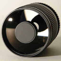
The catadioptric system has also been utilized in the development of telephoto lenses for photography and filmmaking. By incorporating a mirror-lens design, the overall length of the lens is greatly minimized, resulting in much more compact and lightweight lenses with focal lengths of 1000 mm or higher [4]. This reduction in size often leads to a decrease in chromatic aberrations as well due to the fewer number of lenses being used.
Mirror-lens lenses typically do not have adjustable apertures, and their fixed relative aperture ranges from f/5.6 to f/11. As a result, they are best used in well-lit conditions or with highly light-sensitive photographic materials. Some specialized mirror-lens lenses may have extremely high aperture values, such as less than f/1.0. One distinctive characteristic of images taken with a mirror-lens lens is the shape of the out-of-focus scattering circle produced by bright light sources. These sources appear as rings that correspond to the shape of the lens’s entrance pupil. In certain cases, this type of blurring creates a unique and expressive visual pattern. The frequency-contrast characteristic of mirror-lens lenses is relatively low. Despite their compact size and affordability, mirror-lens lenses lost popularity in the early 1970s due to their limited aperture power and soft optical patterns, making way for telephoto lenses with two-component constructions.
The primary benefits and drawbacks of catadioptric systems [edit correct code].
Catadioptric systems offer a combination of mirror and lens systems, providing a range of advantages, but also inheriting a few drawbacks.
- One major advantage is the simplicity of manufacturing a spherical mirror. The corrector addresses spherical aberration by effectively converting it into field curvature aberration.
- In some cases, the aluminized center section of the corrector’s back is utilized as a secondary mirror. This secondary mirror, whether it be the aluminized part of the corrector or a separate component, is securely fixed within the frame. This differs from most reflectors, where the secondary mirror is held by three or four supports, which can result in misalignment and compromise the diffraction pattern. The catadioptric system largely avoids these disadvantages.
- The telescope tube is sealed to prevent contamination of the internal optical components and minimize air currents within the telescope.
- Compared to other telescope designs with the same diameter and focal length, this type of telescope has the most compact tube.
- The manufacturing process for large corrector elements is challenging, limiting the maximum diameter of these instruments to 2 meters.
- These telescopes have a large focal length.
- Because the system includes glass optical elements, there is some chromatic aberration and coma at the edges of the field of view. The corrector glass also absorbs a portion of the light, resulting in a slight reduction in light transmission for the instrument.
- The issue of field curvature was resolved by employing a specialized holder that allows a flat photographic plate to be flexed to the desired curvature. However, it is a challenging and costly task to manufacture a CCD with the necessary curvature.
- The focal length is directly linked to the length of the tube (the distance from the mirror to the corrector is half of the focal length). Moreover, the relative aperture is constrained by residual aberrations.
- Considerable time is required for the thermal stabilization of the optics before commencing observations.
Mirror-lens systems were developed as a means of finding a compromise. However, their applications are limited. Due to their small size and focal length, they are not suitable for astrophysical purposes. Nevertheless, these telescopes have gained popularity among astrometricians.
Also see [ edit edit code ].
Additional information [ edit edit code ]
- ↑ Bykov B. Z., Perov V. A. Formalization of optical parts’ working drawings and selection of tolerances for their characteristics. – 1st edition. – M.: Bauman Moscow State Technical University, 2009 . about the book
- ↑ “Zerochromat” by John Wall
- ↑ Sikoruk L. L. Telescopes for amateur astronomers. – 2nd edition. – Moscow: “Nauka”, 1982. – p. 49. – 368 pages . about the book
- ↑General Course of Photography, 1987, p. 15
- ↑Kudryashov, 1952, p. 56.
Literature [ edit correct code ].
- Fomin A. В. § 5. Photographic Lenses // General course of photography. – 3rd ed. – M. “Legprombytizdat”, 1987. – Pp. 12-25. – 256 p. about the book
- N. Kudryashov Narrow-film cinematographic apparatus //. “How to make and show a movie by yourself”.. – 1st ed. – M. Goskinoizdat, 1952. – Pp. 56-57. – 252 p. about the book