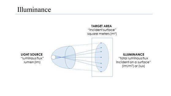
Within the field of photometry, illuminance refers to the overall amount of light that falls on a particular surface, divided by the surface area. It serves as a measurement of the extent to which incident light brightens a surface, taking into account a wavelength-weighted luminosity function that corresponds to an individual’s perception of brightness. In a similar vein, luminous flux denotes the amount of light that is emitted by a surface per unit area. Luminous flux is also commonly referred to as luminance. [1]
These quantities are typically quantified in derived SI units such as lux (lx), or alternatively in lumens per square meter (lm -m -2 ). In the CGS system, illuminance is measured in photos, with one photo equaling 10,000 lux. The foot-candle, a non-metric unit of illuminance, is often used in the field of photography. [2]
Illuminance, previously known as luminance, was often mistakenly associated with other meanings of the word, such as luminance. It is important to note that the term “brightness” should only be used to describe physiological sensation and light perception, and not for quantitative purposes.
The human eye has the capability to perceive objects even in low light conditions, such as starlight at 5 × 10 -5 lux. On the other hand, it can also handle extremely bright conditions, allowing us to read large text at 10 8 lux, which is equivalent to approximately 1000 times the intensity of direct sunlight. However, prolonged exposure to such intense light can be uncomfortable and result in residual images. [citation needed]
Levels of general lighting
| Full daylight | 1,000 [3] | 10,000 |
| Cloudy day | 100 | 1,000 |
| Very dark day | 10 | 100 |
| Twilight | 1 | 10 |
| Deep twilight | 0.1 | 1 |
| Full moon | 0.01 | 0.1 |
| Quarter moon | 0.001 | 0.01 |
| Starlight | 0.0001 | 0.001 |
In the field of astronomy, the brightness of stars as seen from the Earth’s atmosphere is referred to as their luminosity. This luminosity is usually measured in terms of apparent magnitudes in the visible range. [4] To convert these magnitudes to lux, the following formula can be used: [5]
where Ev represents the illuminance in lux and Mv is the apparent magnitude. The inverse conversion can also be performed.
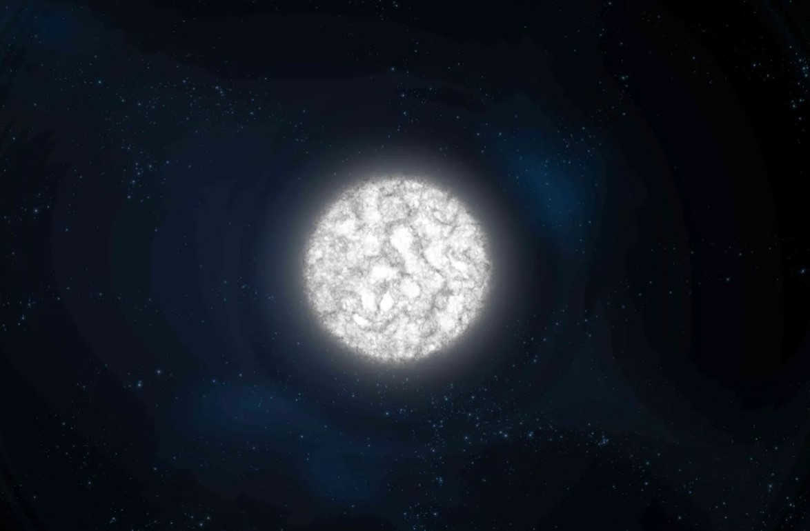
Luminosity and brightness. Visible and absolute stellar magnitudes.
The information regarding celestial bodies is provided through the reception of light. Stars, asteroids, and certain other objects are observed as concentrated sources of illumination. Their emissions are defined by their luminosity. In objects that possess varying angular sizes, the measure of radiation, in addition to luminosity, is known as brightness.
Brightness refers to the amount of radiation that passes through a unit area, perpendicular to a given direction, and is enclosed within a unit solid angle in contact with the emitting surface.
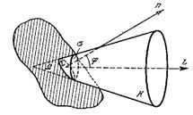
Figure 51. Illumination of the emitting surface.
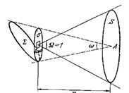
Figure 52. The brightness generated by an object
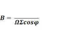
(10)
Σ – luminous surface element.
Ф – is the luminous flux emitted by the surface Σ within a cone with solid angle Ω.
φ – angle between the axis of the cone and the normal to the luminous surface.
During visual observation, the retina is illuminated.
(11)

– Diameter of the pupil.
The maximum brightness produced by an object E = B ω.
ω is the angle at which the object is visible in the sky.
The strength of the visible radiation of light sources is determined by the brightness they create Е.
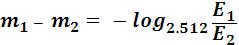
Luminance is the brightness created by the light source on the receivers of radiant energy (eye, photographic plate, photocells, etc.). But brightness is measured in lux, while brilliance is measured in relative units called stellar magnitude, denoted m. The greater the luminance of a light source, the smaller its stellar magnitude.
Estimating the brightness of a star’s magnitude for the first time prior to the second century BC, was accomplished by the ancient Greek astronomer Hipparchus. He classified objects into 6 categories based on their stellar magnitudes. This classification is based on the human eye’s ability to distinguish between sources with a radiation intensity difference of approximately 2.5 times. However, this understanding only emerged in the 18th century.
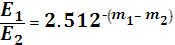
The brightness levels of objects… – 5 m , – 4 m , – 3 m , -2 m , – 1 m , 0, 1 m , 2 m , 3 m … follow a decreasing geometric progression with a common ratio of 2.512.
The star’s magnitude is the logarithm, with a negative sign, of the base 2.512, representing the illumination produced by the object on the surface perpendicular to the rays.
(12)
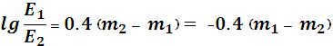
The difference between stellar magnitudes:
; (12.1)
(12.2)
(13)
Pogson’s formula, introduced in 1856, calculates the difference in stellar magnitudes based on a difference in luminosity of exactly 100 times.
(14)
The O m star produces an illuminance of 2.54 * 10 -6 lux at the Earth’s atmosphere boundary, which is equivalent to 1 candela (Kd) from a distance of 600 m. It generates a flux of 10 6 quanta per 1 cm 2 per second across the entire visible spectrum. In the terrestrial ray region, specifically in the wavelength range of 1 Å, it yields 10 3 quanta per 1 cm 2 per second. The Sun, when directly overhead, produces an illuminance of 137000 lux.
Absolute stellar magnitude
Visible stellar magnitudes “m” do not determine the total radiant energy or surface brightness. It is possible for a nearby cold star to have a smaller apparent stellar magnitude than a distant hot star.
In order to compare stars, their fluxes and luminosities must be adjusted to the same distance.
The chosen standard distance is 10 parsecs. Absolute stellar magnitude M is the stellar magnitude that a star would have if it were at a distance of 10 parsecs.
Stellar magnitude
Stellar magnitude is a dimensionless numerical characteristic that measures the brightness of an object. This term is commonly used to describe celestial luminaries. The stellar magnitude is used to determine the energy flux, which is the energy of all photons per second, per unit area. This measurement is important in assessing the luminosity of a celestial luminary. According to the stellar magnitude scale, the formula for calculating the magnitude is m = 2.5lgE + const. A change in stellar magnitude by one is equivalent to a change in brilliance by a factor of 2.5. It is worth noting that there are different types of stellar magnitude, including visual and photographic magnitude. This information is sourced from Wikipedia and the Encyclopedic Dictionary.
STELLAR MAGNITUDE – a measure of the brightness of a celestial object, specifically the amount of light it emits on a plane perpendicular to the incident rays. The most luminous stars fall into the range of 0 to 3 on the stellar magnitude scale, while the faintest stars visible in the night sky have a magnitude of 6 or higher. This information is sourced from the Large Encyclopedic Polytechnic Dictionary.
Absolute stellar magnitude (M) is a term used to describe the apparent magnitude of a star if it were located 10 parsecs away from the observer. Absolute bolometric magnitude takes into account the total emission of electromagnetic waves across all wavelengths. This information can be found on Wikipedia.
Stellar brightness that can be seen – (sometimes referred to as “stellar magnitude”) is a numerical measure of the amount of light emitted by an object in the sky, typically a star, as observed from a specific location. The visible stellar magnitude is influenced by various factors, not just the distance between the object and the observer. The visible stellar magnitude is determined by direct observation and is based on the sensitivity of the human eye to different wavelengths of light, with the maximum sensitivity occurring at a wavelength of 0.55 μm. * * * * * The visible magnitude of a star that can be seen with the naked eye… … Encyclopedic Dictionary
Bolometric stellar magnitude is a parameter that describes the total flux of electromagnetic radiation emitted by an object in space across the entire range of wavelengths. It is calculated by adding the visual stellar magnitude to a bolometric correction, which is always a negative value. This correction factor is determined … … Encyclopedic Dictionary
Absolute stellar magnitude is a measure that characterizes the luminosity of a celestial body. It is used to quantify the brightness of a star based on its intrinsic luminosity. For more information, refer to Stellar magnitude … Big Soviet Encyclopedia
Bolometric stellar magnitude is another term for Stellar magnitude. For further details, consult the Big Soviet Encyclopedia
ILLUMINANCE
Illumination is an abstract noun that means something is illuminated. It also refers to the degree of illumination of a surface or space.
LIGHTING
Illumination can also refer to the degree or area of illumination.
ILLUMINATION
Illumination can be synonymous with light, exposure, or glow. In the ASIS Synonyms Dictionary, there are a total of 7 synonyms for illumination, including illumination, light, exposure, glow, solar illumination, sunshine, and exposure.
ILLUMINATION
“. Illuminance (E) is the ratio of luminous flux to the area of the surface it illuminates; measured in lux (lx). “Source: “MU 2.2.4.706-98/MU OT RM . watch
LIGHT INTENSITY
Light intensity refers to the amount of luminous flux that falls on the surface it illuminates. It is measured in lux (lx) and is an indicator of the brightness of the light source. watch
LUMINOSITY
Light intensity received by a unit area of a lit surface. The illuminance is measured in lux (lx). Source: Handbook of Road Terminology. Observe.
LIGHTING
Prefix – O; root – SWEET; suffix – ENN; suffix – OST; zero ending; Word base: OSVESCENTNESS. Word formation method: Pristavo. Observe.
LIGHTING
The illuminance is the measurement of the amount of light flux per unit area of a surface that is evenly illuminated. It is directly proportional to the intensity of the light and inversely proportional to the square of the distance between the light source and the illuminated surface. The illuminance is a crucial factor in determining the level of exposure. Luxmeters are the instruments used to measure illuminance. This information is taken from the Concise Explanatory Dictionary on Polygraphy (2010). Synonyms for illuminance include illuminance, light, exposure. Please keep in mind that this is a watch.
watch
LIGHTING
Illuminance refers to the amount of light flux that is received by a unit of illuminated surface. This measurement is typically done using a luxmeter. The fundamental units of illuminance are lux and phot. The amount of illuminance on a surface is directly influenced by the brightness of the light source. It is also inversely affected by the square of the distance between the surface and the light source. Additionally, the angle at which the surface is inclined in relation to the direction of the light rays, as determined by the law of cosine, has an impact on illuminance.
. watch
LUMINOSITY
The luminosity is the amount of light that is emitted, reflected, or refracted by a surface and is measured in candlepower per square meter. The illuminance is directly connected to the brightness of a surface in relation to its reflectance. Therefore, luminance can be calculated using the formula RC/d^2, where R represents the reflectance of the surface, C is the intensity of the light source in candlepower, and d is the distance between the source and the surface. Keep an eye on it.
ILLUMINANCE
Illuminance refers to the amount of light flux that falls on a unit of illuminated surface. It is typically measured using a luxmeter. The main units of illuminance are lux and phot. The illuminance of a surface is directly proportional to the brightness of the light source and inversely proportional to the square of the distance between the surface and the light source. Additionally, it is also influenced by the angle at which the surface is inclined in relation to the direction of the light rays. Keep an eye on it!
LUMINOSITY
– The measurement of illuminance at a specific point on a surface, luminosity is calculated by dividing the light flux of radiation that falls on a small surface element containing the point by the area of the surface. In other words, illuminance is the density of the light flux on a surface. The units of measurement for illuminance are lux (lx) and foot-candles (fot), with 1 foot-candle equal to 10,000 lux. observe
ILLUMINANCE
1) illuminance2) <engin.> illumination3) <opt.> irradiance4) luminositySynonyms: brightness, brightness, light, exposure.
LUMINOSITY
g.intensité f lumineuse good luminosity – bon éclairage mSynonyms: illumination, luminosity, light, exposure
ILLUMINATION
noun. fem. gen. only, sing. h.honey, s.-x.illumination
LIGHTING
g. special. illuminazione, illuminamento m good lighting of streets – una buona illuminazione delle vie lux – unit of lighting – lux m: unità di illuminamento Italian-Russian Dictionary.2003. Synonyms: illumination, lighting, light, exposure. watch
g.illuminance, illumination, luminance, quantity of illumination- retinal illumination- threshold illumination
ILLUMINANCE
a value equal to the ratio of light flux falling on a surface to the area of the illuminated surface. The unit of o. in SI is lux (lx). the extrasystem unit of o. fot (f): 1 f = 104 lux. watch
ILLUMINANCE
Illuminance refers to the intensity of light that falls on a surface and is measured in lux. It is normalized based on the specific visual task being performed.
. watch
ILLUMINANCE
Illuminance is a measurement of the amount of light that falls on a given surface area, expressed in lux and photons. It is typically measured using a luxmeter. watch
BRIGHTNESS
The amount of light intensity on the lit surface; measured in lux; standardized based on the nature of the visual task performed.
ILLUMINATION
– light intensity- brightness- luminosity- lighting- light
LUX LEVEL
Illumination level, illuminance, -i, g. Level of illumination. Adequate o. streets. Sufficient room o. Unit of illuminance (measured in lux 1).
LIGHTNESS
Originally called Illumination in the accusative case, this word is usually used in its singular form. It is of feminine gender and is considered inanimate.
ILLUMINANCE
Synonyms: illuminance, illumination, light, exposure
ILLUMINANCE
Illuminance is a masculine noun with no plural form. In technical terms, it refers to the degree or strength of illumination on a surface or in a space.
Illuminance is the measurement of the light flux that falls on a surface, and it is expressed in lux.
LIGHTING
Luminosity is the term used to describe the amount of light flux that falls on a surface, and it is measured in lux.
LIGHTING
Luminosity refers to the quantity of light flux that falls on a surface, and it is measured in lux.
BRIGHTNESS
Brightness, the quantity of light energy reaching a specific area, quantified in terms of lux.
ILLUMINATION
Brightness g. 1) Refer to illuminated. 2) The level of brightness of a particular area, space.

Today we will discuss a type of variable that plays a crucial role in determining the climate characteristics of a specific region. This variable is known as radiance. Illuminance refers to a measurement of the energy per unit area of solar radiation that falls onto a particular surface. It quantifies the amount of solar radiation received by a surface within a designated timeframe and space.
In this article, we will provide you with comprehensive information about irradiance and emphasize the significance of accurately defining climate types.
Main features
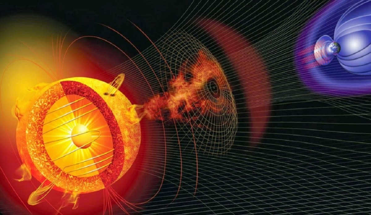
Illuminance is a metric that allows us to measure the amount of solar radiation that reaches a specific surface within a given timeframe. It is important to note that not all solar radiation emitted by the Sun makes it to our planet. Illuminance is typically quantified in terms of power per unit area. The standard unit of measurement is watts per square meter. When discussing solar radiation, we are referring to the quantity of radiation that a particular surface receives over a defined period of time.
For instance, we might state that the illuminance at a particular location is 10 watts per square meter per hour. This means that every hour, one square meter of that location receives 10 watts of solar radiation. By understanding the amount of solar radiation a given surface receives over time, we can determine the prevailing climate in a specific area.
We understand that solar radiation plays a crucial role in determining the temperature of a location. When a place receives a substantial amount of solar radiation, it is expected to have a higher temperature. Furthermore, these radiation levels contribute to the development of prevailing wind patterns and various atmospheric phenomena that lead to precipitation. The sun serves as the catalyst for atmospheric phenomena, including precipitation, within the troposphere. Solar radiation warms up a particular portion of the Earth’s surface, causing the surrounding air to heat up and ascend.
As the air rises, it creates a void that needs to be filled by another mass of air. This process is responsible for establishing wind patterns. The greater the disparity in air densities, the stronger the wind becomes. Moreover, these circumstances are favorable for the formation of anticyclones and storms.
The source of radiation
From a technical perspective, solar radiation reaching the Earth’s surface refers to the time period during which filtered radiation impacts the surface due to the influence of the atmosphere. The information provided by solar radiation on the surface is influenced by factors such as the time of year, latitude, overall climate, and the time of day.
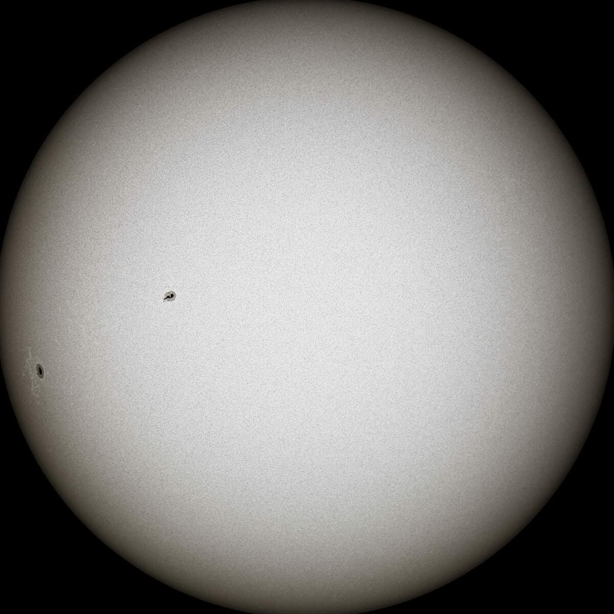
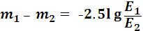
The sun emits electromagnetic radiation, which is the result of the ongoing nuclear fusion reaction occurring within the sun. This reaction involves the combination of two hydrogen nuclei to form a helium nucleus. As a result of this atomic combination, a significant amount of energy is released in the form of radiation.
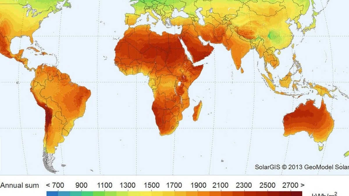
The outer surface of the Sun is approximately 5500 degrees Celsius in temperature. This celestial body releases significant quantities of electromagnetic radiation across a broad spectrum of wavelengths and frequencies. This electromagnetic radiation spans from ultraviolet to infrared, with the portion visible to the human eye being referred to as the rainbow. The solar radiation spectrum encompasses all wavelengths emitted by the Sun, irrespective of their visibility to humans.
Various forms of irradiance
There are different types of irradiance based on their characteristics and sources. Let’s go through each of them in detail:
- Overall solar irradiance: refers to the measurement of all wavelengths per unit of power, impacting the Earth’s upper atmosphere. It is typically measured perpendicular to the incoming sunlight.
- Direct normal irradiance: is the measurement of the amount of solar radiation that reaches the Earth’s surface at a specific location. This measurement is taken using a device positioned at a right angle to the Sun. The total direct illuminance is calculated by subtracting the atmospheric losses, which are caused by the absorption and scattering of light by wind and clouds, from the extraterrestrial illuminance above the atmosphere. The magnitude of these losses can vary based on factors such as the time of day, latitude, cloud cover, humidity, and other environmental conditions. Д.
- Global horizontal irradiance: The measurement of the total radiation from the sun on the Earth’s horizontal surface is known as global horizontal irradiance. It is determined by combining direct radiation and diffuse horizontal radiation.
These values are crucial for understanding the climate conditions of a specific location. They are also utilized in various research studies to develop and implement renewable energy sources that harness the power of the sun. One example of this is photovoltaic solar energy. To assess the feasibility of using photovoltaic solar energy, it is essential to determine the amount of solar radiation that will impact a house’s roof surface throughout the year. Additionally, data on other variables like cloud cover, humidity, and wind patterns are necessary.
I trust that this information will enable you to gain a deeper understanding of the concept of illumination.
This article has been written in adherence to our editorial ethics guidelines. If you find any errors, please click here to report them.
Summary of the Full Article: Network Meteorology “Meteorology” Science “Illumination“
Within this paragraph, we will explore the practice of amateur photometric observations of ISVs, which involves quantitatively measuring the reflection of the Sun’s light from an ISV [99]. These observations serve two main purposes: determining the configuration of satellite solar panels and determining the rotation period of certain satellites. Furthermore, we will also delve into some of the more unique applications of ISP photometry that are accessible to amateur enthusiasts. The Appendices contain a transcription of the international standard format known as the “PPAS” format, which is utilized for providing photometry.
To start, let’s examine some characteristics of the visible movement of an ISV across the observer’s sky. As an illustration, let’s consider the inaugural Soviet meteorological satellite that was launched on August 28, 1964, known as Cosmos-44 (SCN: 876) [94] — the pioneering meteorological satellite of the Meteor series [95]. The image below, shown in Figure 1, captures the fifth satellite of the Meteor series, Cosmos-122.
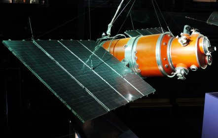 |
| Figure 1. Cosmos-122 (SCN: 2254) — the fifth Meteor satellite of the Meteor series [95]. |
| Fig. 2. The elevation of the Cosmos-44 (SCN: 876) satellite changes according to Heavensat calculations over time. Time is measured in seconds since sunrise. |
The distance between the ISV and the observer varies in a more predictable manner (cf. Fig. 3) – almost linearly, except for the period of closest approach to the observer.
| Figure 3. Heavensat-calculated change in the distance between the observer and ISB for Cosmos-44 (SCN: 876) over time. Time is measured in seconds since sunrise. |
The above graphs demonstrate that as the satellite gets closer, it gains altitude at a faster rate. This is a predictable observation, as we are all aware of the concept of perspective which can distort the perceived speed of objects in space.
Angle of Phase.
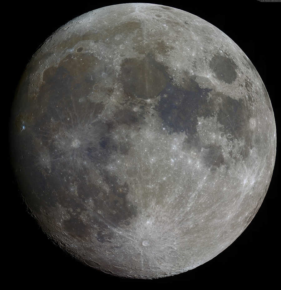
To further explore the question of how the satellite’s light changes during flyby, we need to understand the concept of phase angle. The phenomenon of moon phases is familiar to everyone – new moon, first quarter, full moon, and third quarter. However, these four phases alone are not sufficient to describe the visible illuminated portion of the moon. In astronomy, the concept of phase is introduced, which represents the ratio of the area of the visible illuminated part of the moon to the area of the entire lunar disk. A phase of “0” corresponds to the new moon, a phase of “0.5” corresponds to the first and third quarters, and a phase of “1” corresponds to the full moon. However, when calculating the light of a satellite, the phase angle becomes crucial. The phase angle is the angle between the center of the Sun, the satellite, and the observer (see Fig. 4). When the phase angle (ψ) is 0 degrees, the satellite is located on the Sun-observer-satellite straight line, behind the observer, and is maximally illuminated (phase 1.0). On the other hand, when the phase angle (ψ) is 90 degrees, only half of the satellite is illuminated for the observer (phase 0.5).
As the International Space Vehicle (ISV) moves across the observer’s sky, there will be a change in the phase angle and consequently, the phase itself will also change (refer to the example provided in Figure 5). It is well-known that the brightness of the Moon varies during different phases. Calculations [107] indicate that at a phase angle of ψ = 0°, the Moon’s luminosity is -12.3 m, while at ψ = 90°, it decreases to -11 m. Furthermore, at ψ = 170°, the Moon’s brightness drops to -4.1 m, making it visible as a thin crescent. The phase of the body, denoted by Ф, and the phase angle, denoted by ψ, are connected through a simple relationship: F = cos 2 (ψ/2). A phase value of F = 1 (referred to as “full moon”) corresponds to a phase angle of ψ = 0°, a phase value of F = 0.5 (referred to as “first/third quarter”) corresponds to a phase angle of ψ = 90°, and a phase value of F = 0 (referred to as “new moon”) corresponds to a phase angle of ψ = 180°. An animation demonstrating this phenomenon is displayed below.
Based on this information, we can infer that the satellite’s brightness will not only change because of the distance between the satellite and the observer, but also because of the variation in the phase angle of the satellite.
| Figure 5. Heavensat has calculated the change in phase angle over time for the Cosmos-44 satellite (SCN: 876). The time is measured in seconds since sunrise. |
Variation in satellite brightness during flyby.
We are now on the verge of resolving the issue of calculating the luminosity of an ISV as it traverses the observer’s sky. The changes in brightness can be determined using the Heavensat program, as shown in Figure 6. Figure 6. The discrepancy in the graph for DELTA 1 R/B is attributed to the fact that it was outside of the Earth’s shadow at the beginning of its trajectory (refer to the information below) and its brightness was not computed.
| Figure 6. Heavensat-computed variation of light over time for Cosmos-44 (SCN: 876), SL-3 R/B (SCN: 877), SL-8 R/B (SCN: 6061), and DELTA 1 R/B (SCN: 7735). Time is measured in seconds from sunrise. |
As previously mentioned, the brightness of the satellite will be determined by the distance “r” from the observer and the phase angle “ψ” OF THE ISV. Additionally, it will also be influenced by the satellite’s surface reflection coefficient, or albedo “A” [108], as well as the area “S” of the satellite’s reflecting surface. Therefore, in the case of a spherical satellite with diffuse reflection (uniform reflection in all directions), we can express the illumination produced by the ISV on the Earth at the observation point during the flyby [101, 104] using the following formula:
where Isun represents the illuminance of the satellite from the Sun in close proximity to the Earth. For more information on formula (1), please refer to Ref. Appendices (“Formulas of the reduced lightness for ISVs”). Figure 7 illustrates the graph of the cos 2 (ψ/2) function. As mentioned earlier, the graph indicates that the maximum brightness occurs at the minimum phase angle (referred to as the “full moon” of the satellite).
Using Pogson’s formula [109] and the Sun’s light value (-26.5 m), we can deduce the relationship between the change in the satellite’s light during the flyby:
The family of curves calculated using equation (2) is shown in Figure 8. These curves depict the brightness of the Cosmos-44 satellite (SCN: 876) at various albedo values, in comparison to the calculated curve m(t) generated by the program “Heavensat”. It is evident that the surface of Cosmos-44 has a relatively low reflection coefficient, approximately 10%.
It is crucial to emphasize that formula (2) is specifically applicable to a spherical satellite with diffuse reflection. This model of reflection is the simplest one, but in reality, there are very few spherical satellites orbiting the Earth without additional elements such as solar panels, antennas, etc., which alter the appearance of the phase function. The phase function, denoted as F(ψ), is represented by the equation F(ψ) = cos 2 (ψ/2) in our simplest case. However, for each satellite, a unique phase function is determined in practice to ensure the observed satellite light change closely matches the calculated one. If the value of albedo A is unknown beforehand, the so-called effective area is often determined based on satellite photometry results. The effective area is the product of the albedo and the actual reflective surface area, i.e., A-S.
For a polished sphere, a polished and diffuse cylinder, and a plate, we can introduce phase functions F(ψ) as displayed in Table 1.
Table 1. Types of phase functions for various reflecting surfaces [142].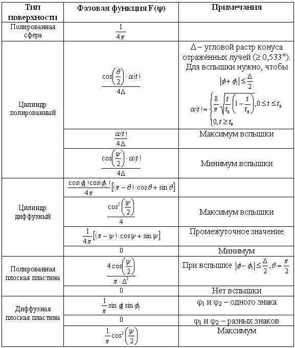 |
In Table 1, the notes also indicate the minimum and maximum values of the function during flashes. In this case, the parameter Δ represents the angle of the reflection cone screen, specifying the angular width of the “sun bunny” transmitted from the satellite to the Earth. The minimum value of Δ≈0.5° is determined by the angular size of the solar disk.
Fig. 10 illustrates the theoretical curves depicting the changes in the reduced light of the satellite (refer to “The reduced stellar magnitude of the satellite” below) based on the phase angle ψ for various reflecting surfaces. It is evident from the graphs that the specular sphere (curve 6) exhibits higher brightness compared to the diffuse sphere (curve 1) only when the phase angle ψ is greater than approximately 90°, while the diffuse sphere will appear brighter at smaller phase angles. The diffuse plate (curve 4) produces the most intense highlights.
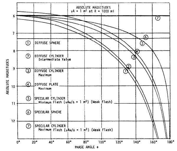 |
| Figure 10. Different reflecting surfaces have theoretical curves that show the dependence of the reduced light of an ISV on the phase angle ψ (the absolute light is determined for the distance r = 1000 miles, i.e., 1609 km) of the effective area A-S = 1 m 2 [142]. |
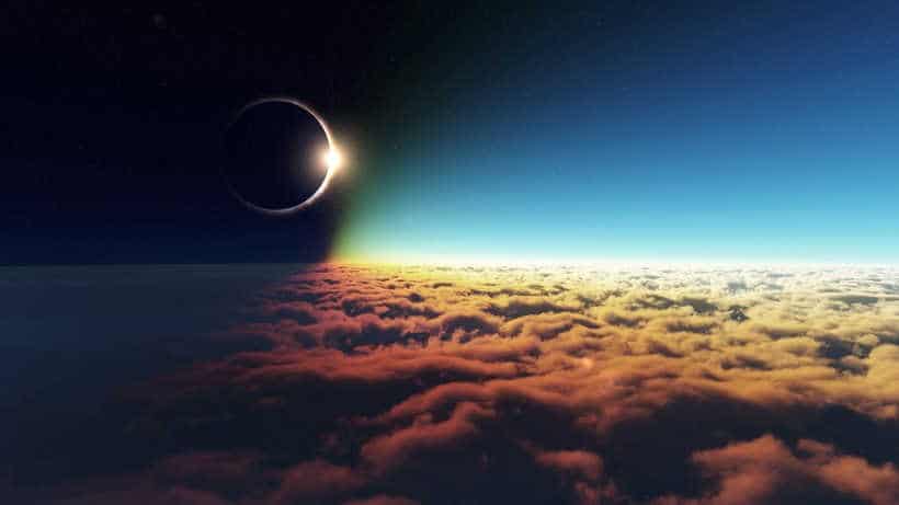
To conclude this paragraph, it is important to note another significant factor that affects the change in the appearance of an ISV. It is a well-known fact that the Sun appears redder when it is lower in the sky, as we can easily observe during a beautiful sunset. One of the reasons why we can appreciate the beauty of a sunset is because the Sun’s brightness is greatly reduced near the horizon compared to its brightness at midday. During a sunset, the Sun does not blind our eyes like it does during the day because its intensity is not as strong. This phenomenon occurs because as the Sun gets closer to the horizon, its rays have to pass through a greater amount of air. The blue rays scatter, leaving behind the yellow-red rays that give the setting Sun its characteristic color. Additionally, the brightness of the Sun’s disk decreases due to the scattering and absorption of its rays in the atmosphere. It is worth noting that the absorption of light in the atmosphere is a characteristic feature of all celestial bodies, including ISVs. The level of absorption, measured in stellar magnitudes, varies depending on the elevation (angular height) of the celestial body above the horizon. This relationship is illustrated in Figure 11, based on data [105]. The graph shows the level of light absorption relative to the absorption at the zenith, which is only 0.21 m for the wavelength region that is most sensitive to the human eye (~550 nm) [105]. These data are applicable at sea level and a pressure of 760 mm Hg.
The chart illustrates that when the altitude reaches approximately 10°, the atmosphere will diminish the shininess of an ISV by 1 m. Conversely, at an elevation of 20°, the atmosphere will only reduce the shininess by 0.43 m. This indicates the necessity of conducting photometric observations of the satellite at elevations of at least 20°-30°. In the field of astronomy, precise photometry is typically not performed at luminosities below 45°-50°, but for our amateur purposes, we can slightly lower this threshold.
In Fig. 12, there are two plots illustrating the changes in light intensity with and without atmospheric absorption (the program “Heavensat” is used for calculating the m(t) curve). It is evident that considering atmospheric absorption causes a separation in the m(t) dependency, particularly pronounced near the boundaries of the graph branches when the satellite is close to the horizon. It’s worth noting that this scenario is an idealization, as the atmosphere always contains dust, small particles, and haze, which can greatly enhance light absorption from the satellite to the observer. Experienced observers can attest that not every clear night offers the same “transparent” sky, especially in urban areas. Additionally, the illumination of the sky by distant and local sources further restricts the observer’s ability to spot the satellite, requiring a certain elevation to do so.
| Figure 12 showcases the light variation plots of the Cosmos-44 (SCN: 876) flyby, both with and without accounting for atmospheric light absorption. |
Displayed is the satellite’s current stellar magnitude.
The derivation of formula (3) can be understood by utilizing formula (1) and taking into account the reduced value of m0 McCants obtains for the distance r0 = 1000 km and phase angle ψ0 = 90°. Consequently, the formula can be obtained:
The comprehensive derivation of formula (4) is provided in the Appendix (“Equations for the diminished light for ISVs”). In spite of the apparent disparity between (3) and (4), they are essentially equivalent.
Let’s wrap up the paragraph with this example below. Let’s witness the passing of an ISV and acquire 130 photometry points – the table [mr i ; t i ], which consists of pairs of brightness numbers and measurement time (for the purpose of this example, the photometry points were computed using the “Heavensat” program). Using the obtained table, we determine the value of m0 for each of the 130 photometry points and create a histogram (Fig. 13).
To create a histogram like this, you can utilize software such as “EXEL”, the free program “QTiPlot” [97], or other data processing programs. Ideally, we would have a singular value for m0. Looking at the histogram, we can see that the value of m0 is 5.0 m ± 0.05 m. In practical terms, this would be considered an excellent result. By the way, the Heavensat program uses the McCants catalog [111] to calculate the brightness of the satellite during the flyby. By checking the “mcnames” file in the ./Data/ directory (which is the McCants catalog), we can confirm that the indicated brightness value for the Cosmos-44 satellite (SCN: 876) is indeed 5 m, matching our obtained result. In actual measurements, apart from averaging the m0 values, the least squares method (LSM) [110] can be employed. For this purpose, we can rewrite formula (4) as mr = f(ψ,r) + m0 and apply the MNC method to determine the sole unknown parameter m0.
Shadow of the Earth.
Let’s now examine another aspect of satellite observation that we encounter in real-world application. Our planet, Earth, is illuminated by the Sun, and as a result, it creates a shadow behind it – an area in space that is shielded from the Sun’s rays. Surrounding the shadow is a penumbra, which is a region partially shielded from sunlight. The process of shadow and penumbra formation is depicted in Figure 14..
The Earth’s shadow covers a significant distance, as demonstrated by periodic lunar eclipses. These eclipses occur because the Moon orbits the Earth at an average distance of 384,400 km, which is much farther than even highly ecliptic ICBMs. In Chapter 2, titled “What Orbits and ICBMs Are There?”, this is discussed further. By performing relatively simple geometric calculations, it can be determined that the Earth’s shadow terminates at a distance of approximately 1,382,030 km from the Earth’s center. This point is labeled as “K” in Figure 12. At this location, the radius of the penumbra, segment “KE”, measures approximately 11,870 km, which is 1.9 times the radius of the Earth. Since satellites orbit the Earth at distances much smaller than 1.4 million kilometers, there is always a possibility of entering or exiting the Earth’s shadow.
Let’s calculate the latitudes of the sub-satellite points (the points on the Earth’s surface where the line from the satellite’s center to the Earth’s center is projected) when the satellite enters and exits the Earth’s shadow (see Fig. 15). Fig. 15). To keep things simple, we will assume that the satellite is moving on the vernal equinox (March 21, when the Sun’s declination δ sun = 0°) in a circular, polar, low orbit at an altitude of “h” above the Earth’s surface. We will consider the Earth as spherical and neglect the convergence of the Earth’s shadow for low satellites. Here’s what we get: the satellite enters the Earth’s shadow at point C and is projected onto the Earth’s surface at point B simultaneously. The latitude of point B is the angle MOB = α. From triangle CAO, we can find that cos(β) = AO/OC = R/(R + h), where R is the Earth’s radius and h is the satellite’s height above the Earth’s surface. Since angle MOA is a right angle, the latitude α = 90° – β, or finally: α = 90° – acrcos(R/(R + h)). For a satellite in a circular orbit with an altitude of h = 500 km, the latitude α = 68°S. The sub-satellite point of exit from the shadow will be symmetric – 68°N. On the day of the winter solstice, the Sun is displaced to the south by the value of its maximum declination δ sun = -23.5°, and the Earth’s shadow rises by the same angle δ sun upward. Therefore, for a satellite in a circular orbit with a height of h = 500 km, the sub-satellite point of entry into the Earth’s shadow will have a latitude α = 68 ° – 23.5 ° = 44.5 ° S, and the point of exit will shift to the north pole – 91.5 °, even crossing the north pole. On the day of the summer solstice, the situation will be reversed.
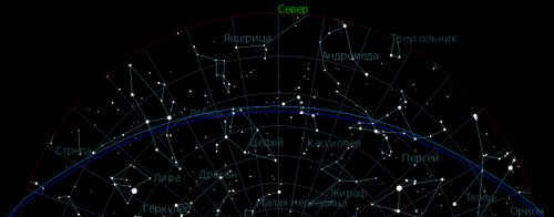
These straightforward calculations demonstrate that depending on the time of year, there will be sections of the sky at night that are obscured by the Earth’s shadow. As a result, even under ideal conditions for observing an ISV, a portion of its path will be in the shadow. It will either emerge from the shadow abruptly or vanish swiftly in the middle of the sky once it enters the shadow. Summer in the middle latitudes of the northern hemisphere offers the most favorable season for observing ISVs. The Earth’s shadow does not rise high above the horizon in the southern part of the sky, and the Sun does not sink too far below the horizon, creating optimal conditions for ISV observation. This means that smaller phase angles are available, resulting in brighter satellites. However, the downside is that due to the Sun’s low position below the horizon, nights from mid-May to mid-July are not experienced in mid-latitudes, resulting in minimal darkness and insufficiently dark skies. Figure 15 depicts the position of the Earth’s shadow and penumbra in the sky at local midnight on the summer solstice (June 21) for a latitude of 54°N. The Earth’s shadow does not rise beyond 18° above the southern point (calculations performed using the “Heavensat” program).
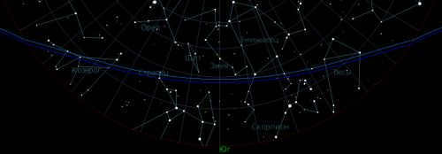 |
| Figure 16. The Earth’s shadow and penumbra’s position in the sky during local midnight on the summer solstice (June 21) at a latitude of 54°N. |
During winter, there is a significant change in the situation. Close to the day of the summer solstice, at local midnight in the middle latitudes of the northern hemisphere, the entire sky is covered by the Earth’s shadow. The Sun goes deep below the horizon during the night, making the evening and morning the most favorable times to observe the ISR. In spring and fall, the situation is somewhere in between winter and summer. The Earth’s shadow covers most of the sky at local midnight, but the duration of satellite visibility is longer compared to winter. In Figure 17, the position of the Earth’s shadow and penumbra in the sky at local midnight on the vernal equinox (March 21) is depicted for latitude 54°N. The Earth’s shadow covers almost the entire sky from the south, reaching a point north of 25°.
 |
| Fig. 17: The Earth’s shadow and penumbra’s position in the sky and local midnight on the vernal equinox day (March 21) for latitude 54°N. |
Watching the shadow’s position on the program “Shadow & Satellite” [113] is much more convenient – it creates a “grid” of satellites in the sky and shows the Earth’s shadow position and the phases of the satellites (cf. Fig. 18), as well as calculates the zenith distance of the shadow edge (“Minimum z” and “Maximum z” in the figure) – see Fig. 15. Fig. 15These angles are represented by ZFD and ZFC, respectively.
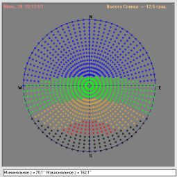 |
| Figure 18: The Earth’s shadow and penumbra’s location in the sky and the local midnight on the summer solstice (June 21) for a latitude of 54°N and a longitude of 27.5°E, as shown in the “Shadow & Satellite” program. |
If there was no atmosphere on Earth, any object in the Earth’s shadow would be completely devoid of light (excluding any faint illumination from stars). However, due to the presence of an atmospheric layer surrounding the Earth, the sun’s rays are bent as they pass through the Earth’s outer edge, allowing some of the light to reach the shadowed area (refer to Figure 19). Figure 19). The degree of refraction is approximately 2° [102]. Amateur astronomers are aware that even during a total lunar eclipse, the Moon’s surface does not turn completely black, but instead takes on a dark red hue. This red tint is caused by the refraction of red light from the Sun in Earth’s atmosphere at the outer edge.
In Fig. 21, we can see a photo taken by amateur astronomer Andrei Oleshko (Russia) [103], capturing the Moon passing through the Earth’s shadow during the lunar eclipse on August 16-17, 2008. This image reveals that the boundary of the Earth’s shadow is not well-defined but rather blurred, which can be attributed to the way the Sun’s rays are refracted in the Earth’s atmosphere.
When an ISV is positioned 500 km above the Earth’s surface, the angular distance between the edge of the penumbra and the shadow is approximately 1°-1.5° (refer to Fig. 17 – 18). The disparity between the two increases with higher satellite orbits due to the narrowing of the shadow cone and the widening of the penumbra cone as they move away from the Earth.
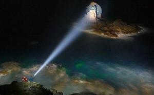
However, the brightness of satellites diminishes rapidly to nearly zero when they enter the Earth’s shadow, even for the brightest International Space Vehicles (ISVs) like the International Space Station (ISS). The Moon’s faint glow, which is clearly visible during low lunar phases, is not present in the Earth’s shadow due to the Sun being behind the Earth’s disk. In Figure 22, a photograph taken by Anatoly Grigoriev (Gubkin, Russia) on April 14, 2012, using the digital mirror camera “Canon EOS 1000D”, with the lens “Mir-1” 2.8/37, ISO 800, and a shutter speed of 32 seconds, captures the ISS entering the Earth’s shadow.
For a more detailed analysis of the trajectory, Figure 23 displays the photometric profile of the ISS track. It can be observed that the satellite’s brightness decreases almost linearly across a significant portion of the track when entering the shadow.
Fig. 24, obtained from observations by P. Sukhov (JSC ONU, Ukraine) at the Odessa Astronomical Observatory at Mayaki using a 50 cm telescope of the Cassegren optical system with an electrophotometer at the focus [100], provides another instance of how the brightness of a satellite changes as it enters or exits the shadow. During the observation period, the E-Bird satellite (SCN: 27948), which is in geostationary orbit, gradually lost its light in a near-linear fashion as it entered the Earth’s shadow.
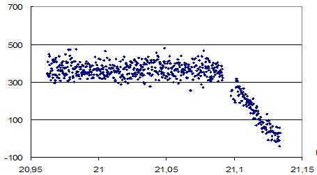 |
| Figure 24. Fragment of the brightness pattern of the celestial object known as “E-Bird” (SCN: 27948) during its passage through the Earth’s shadow (in relative units). Integrated color. October 5, 2005, Universal Time (UT) is shown on the horizontal axis, counts after background subtraction are shown on the vertical axis [100]. |
Earlier, we discussed the main characteristics of the movement of an ISV across the observer’s field of view and the corresponding changes in the satellite’s brightness caused by these factors. Now, we can proceed to examining specific types of photometric observations.
© BelAstro.Net, Lupus, April 15, 2012
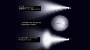
The luminous flux represents the amount of light energy emitted by a singular source, and it is measured in terms of spatial angles due to its dependence on distance.
Lumen is a unit of measurement that quantifies the power of light radiation, taking into account the human eye’s perception of light sensation.

The unit of light flux, known as the lumen, represents the total quantity of light. To illustrate, a 40-watt incandescent bulb generates a luminous flux equivalent to 415 lumens, while a fluorescent bulb emits a flux of 3200 lumens. Regardless of the optical system surrounding the light source, the quantity of light (measured in lumens) remains constant. Consequently, unless the number of lumens is provided for a non-directional light source, its illuminating capacity remains uncertain.
Illuminance is a measure of the amount of light that falls on a specific surface area. It is influenced by the wavelength of the light, as the human eye perceives different wavelengths with varying brightness. Illuminance is calculated separately for different wavelengths. The colors perceived as the brightest by humans are green, which has a wavelength of 550 nanometers, followed by yellow and orange. Colors such as red, blue, and violet have shorter or longer wavelengths, making them appear darker. The concept of illuminance is often associated with brightness. When a lamp illuminates an area, a larger surface area will be less brightly illuminated compared to a smaller area.
Distinguishing between brightness and illuminance

In astronomy, the concept of brightness has two meanings in the Russian language. Brightness refers to a characteristic of luminous bodies, which is a physical quantity. It also describes a subjective idea that is influenced by various factors, such as:
The lower the amount of light in the surroundings, the more intense the light source appears to us. It is important to differentiate between brightness and illuminance and keep in mind the following:
- Brightness pertains to the light that is reflected from the surface of a luminous object;
- Illuminance refers to the light that falls onto an illuminated surface.
Luminosity in the field of astronomy encompasses two ideas: the radiation emitted by stars and the reflection of light by planets. Within this scientific discipline, the brightness of stars is quantified using a photometric scale, in which a higher brightness is associated with a lower magnitude. Stars with the highest brightness have a negative magnitude.
Measurements are taken in units of lux and candela
The measurement of luminance in astronomy is known as illuminance, and it is expressed in candela per square meter. This unit is commonly used for various applications and physiological purposes.
When it comes to calculating the levels of illuminance, the unit of measure used is lux. One lux is equivalent to one lumen per square meter. Another unit of measure used is the foot-candle, which is commonly used in fields such as film, photography, and others. The term “foot” in foot-candle refers to the unit of measurement being based on the illuminance of a square foot of surface area, measured over a one-foot interval.
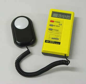
Photometer
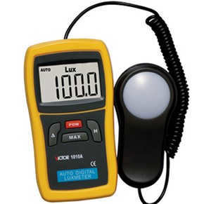
A photometer is a device used to measure light intensity. It works by detecting light and converting it into an electrical signal, which is then measured. Photometers are commonly used to read light levels in lux, although there are some that use other units. These devices, also known as exposure meters, are essential for photographers and operators as they help determine the appropriate shutter speed and aperture settings. Furthermore, photometers are also utilized in various other fields such as crop production and museums, where maintaining the right amount of light is crucial.
Working in a room with insufficient lighting can cause a range of health issues, such as vision impairment, depression, and other physical and mental disorders. That’s why workplace regulations on occupational health and safety include requirements for minimum safe illumination. A photometer’s measurement output provides information on the extent of light distribution in a given area, ensuring that the entire room receives adequate illumination.
Light Flow and Museum Displays

The rate of deterioration and fading of museum exhibits is influenced by the level of illumination and the intensity of the flux emitted by the light source. Museum personnel are responsible for assessing the illuminance of the exhibits in order to ensure that the amount of light flux per museum unit is within safe limits and that visitors have adequate illumination when observing the exhibits.
By analyzing light level readings, it is possible to ascertain the camera exposure. Determining the light level of an exhibit is a straightforward process that involves basic calculations. Museum personnel often rely on a formula or reference a table that presents the exposition in illumination units. When performing these calculations, it is important to consider that the camera absorbs a certain amount of light, which must be taken into account.
Light Intensity in Horticulture and Crop Production
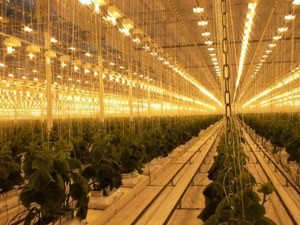
Prior to supplying a plant with the illumination required for the process of photosynthesis, it is imperative to possess knowledge regarding the specific light requirements of each particular crop. This information is commonly known by horticulturists and botanists, who utilize photometers to measure light levels and ensure that each individual plant receives the optimal amount of light for its growth and development.
Modern photometers convert light radiation into electrical impulses and record them using the principles of an ammeter and voltmeter. These impulses are then converted into a computer format.
A photometer is a versatile instrument used in various fields of knowledge including chemistry, molecular biology, physics, materials science, and more. It is widely employed in industries that deal with laser and optical products. Additionally, photometers have applications in forensic laboratories.
Therefore, based on the information provided above, it is crucial to purchase lamps with a specified number of lumens. It is important to note that illuminance and brightness are distinct concepts, and the amount of light can be precisely measured with a specialized photometer.